Peter Lobner, updated 21 February 2021
1. Background
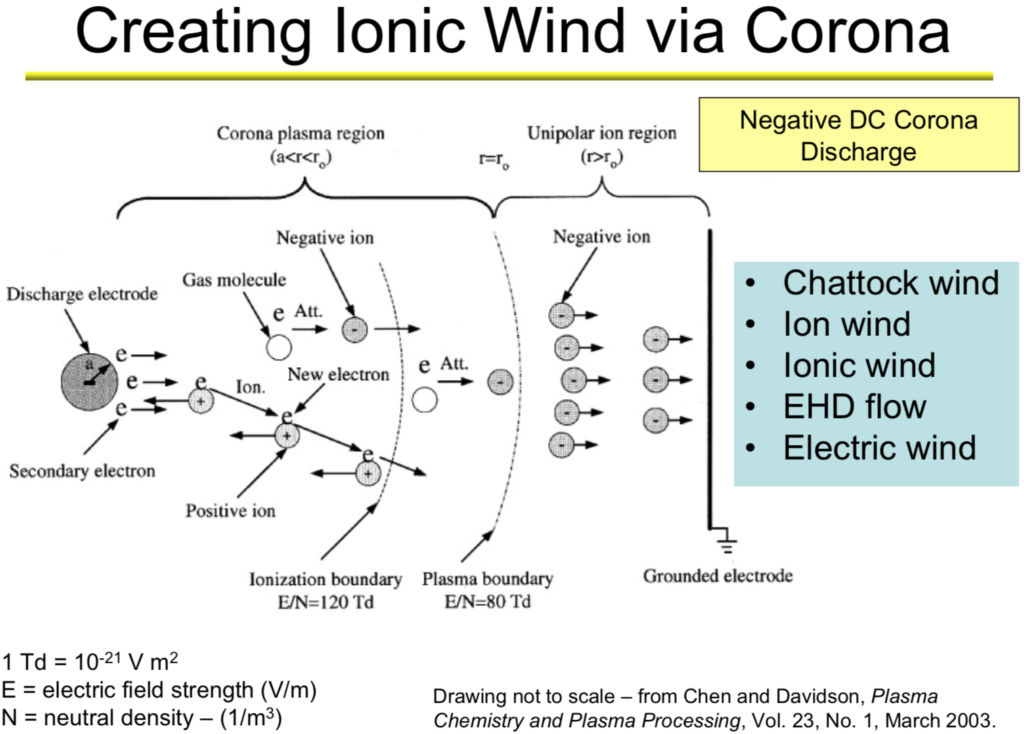
When charged molecules in the air are subjected to an electric field, they are accelerated. When these charged molecules collide with neutral ones, they transfer part of their momentum, leading to air movement known as an “ionic wind.” This basic process is shown in the following diagram, which depicts a strong electric field between a discharge electrode (left) and a ground electrode (right), and the motion of negative ions toward the ground electrode where they are collected. The neutral molecules pass through the ground electrode and generate the thrust called the ionic wind.
This post summarizes work that has been done to develop ionic wind propulsion systems for aircraft. The particular projects summarized are the following:
- Major Alexander de Seversky’s Ionocraft vertical lifter (1964)
- Michael Walden / LTAS lighter-than-air XEM-1 (1977)
- Michael Walden / LTAS lighter-than-air EK-1 (2003)
- The Festo b-IONIC Airfish airship (2005)
- NASA ionic wind study (2009)
- The MIT electroaerodynamic (EAD) heaver-than-air, fixed wing aircraft (2018)
In addition, we’ll take a look at recent ionic propulsion work being done by Electrofluidsystems Ltd., Electron Air LLC and the University of Florida’s Applied Physics Research Group.
2. Scale model of ion-propelled Ionocraft vertical takeoff lifter flew in 1964
Major Alexander de Seversky developed the design concept for a novel aircraft concept called the “Ionocraft,” which was capable of hovering or moving in any direction at high altitudes by means of ionic discharge. His design for the Ionocraft is described in US Patent 3,130,945, “Ionocraft,” dated 28 April 1964. You can read this patent here: https://patents.google.com/patent/US3130945A/en
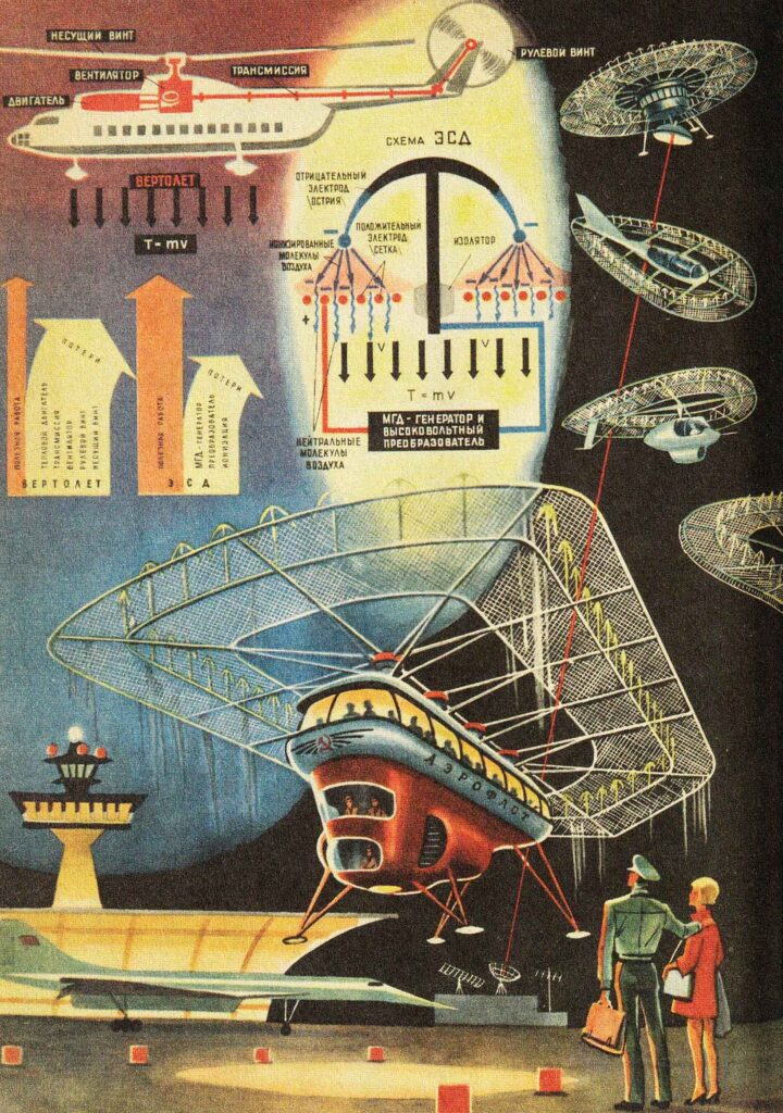
The operating principle of de Seversky’s Ionocraft propulsion system is depicted in the following graphic.
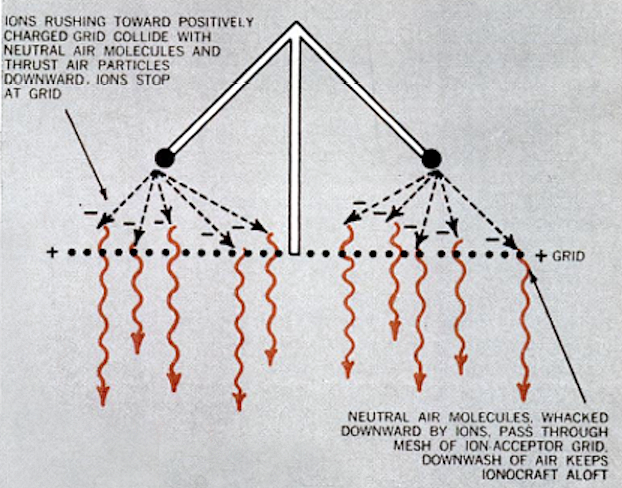
Source: Popular Mechanics, August 1964
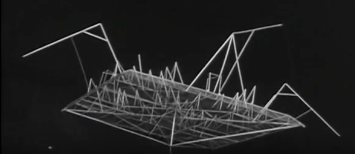
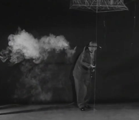
In 1964, de Seversky built a two-ounce (57 gram) Ionocraft scale model and demonstrated its ability to fly while powered from an external 90 watt power conversion system (30,000 volts at 3 mA), significantly higher that conventional aircraft and helicopters. This translated into a power-to-weight ratio of about 0.96 hp/pound. You can watch a short 1964 video of a scale model Ionocraft test flight here:
De Seversky’s Ionocraft and its test program are described in an article in the August 1964 Popular Mechanics magazine, which is available at the following link: https://books.google.com/books?id=ROMDAAAAMBAJ&printsec=frontcover&source=gbs_ge_summary_r&cad=0#v=onepage&q&f=false

Source: Popular Mechanics Archive, August 1964
Source: Popular Mechanics Archive, August 1964
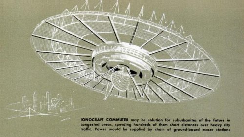
Technology for Youth magazine, 1969, Issue 7.
In the 1960s, engineers found that Ionocraft technology did not scale up well and they were unable to build a vehicle that could generate enough lift to carry the equipment needed to produce the electricity needed to drive it.
3. The first free-flying, ion-propelled, lighter-than-air craft flew in 1977: Michael Walden / LTAS XEM-1
The subscale XEM-1 proof-of-concept demonstrator was designed by Michael Walden and built in 1974 by his firm, Lighter Than Air Solar (LTAS) in Nevada. After leaving LTAS in 2005, Michael Walden founded Walden Aerospace where he is the President and CTO, building on the creative legacy of his work with the former LTAS firms. The Walden Aerospace website is here: http://walden-aerospace.com/HOME.html
The basic configuration of this small airship is shown in the following photo. The MK-1 ionic airflow (IAF) hybrid EK drives are mounted on the sides of the airship’s rigid hull.
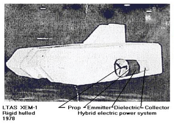
hybrid EK drive. Source: Walden Aerospace.
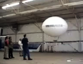
XEM-1 originally was tethered by cable to an external control unit and later was modified for wireless remote control operation. In this latter configuration, XEM-1 demonstrated the use of a hybrid EK propulsion system in a self-powered, free-flying vehicle.
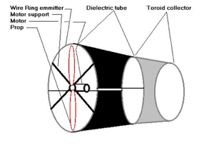
Walden described the MK-1 IAF EK drive as follows: “The duct included a 10 inch ‘bent tip’ 3-bladed prop running on an electric motor to create higher pressures through the duct, making it a ‘modified pressure lifter’…. The duct also had a circular wire emitter, a dielectric separator and a toroidal collector making it a ‘toroid lifter’.”
The later MK-2 and MK-3 IAF EK drives had a similar duct configuration. In all of these EK drives, the flow of ions from emitter to collector imparts momentum to neutral air molecules, creating usable thrust for propulsion. You’ll find more information on the MK-1 IAF EK drive and later versions on the Walden Aerospace website here: http://walden-aerospace.com/Waldens_Patents_files/Walden%20Aerospace%20Advanced%20Technologies%2011092013-2.pdf
The XEM-1 was demonstrated to the Department of Defense (DoD) and Department of Energy (DOE) in 1977 at Nellis Air Force Base in Nevada. Walden reported: “We flew the first fully solar powered rigid airship in 1974, followed by a US Department of Defense and Department of Energy flight demonstration in August 1977”…. “ DoD was interested in this work to the extent that some of it is still classified despite requests for the information to become freely available.”
Walden credits the XEM-1 with being the first fully self-contained air vehicle to fly with a hybrid ionic airflow electro-kinetic propulsion system. This small airship also demonstrated the feasibility of a rigid, composite, monocoque aeroshell, which became a common feature on many later Walden / LTAS airships.
4. The second free-flying, ion-propelled, lighter-than-air craft flew in 2003: Michael Walden / LTAS EK-1
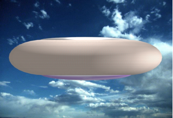
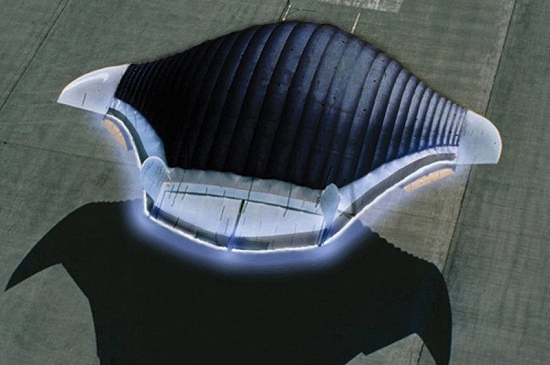
Michael Walden designed the next-generation EK-1, which was a remotely controlled, self-powered, subscale model of a lenticular airship with a skin-integrated EK drive that was part of the outer surface of the hull. The drive was electronically steered to provide propulsion in any direction with no external aerodynamic surfaces and no moving parts.
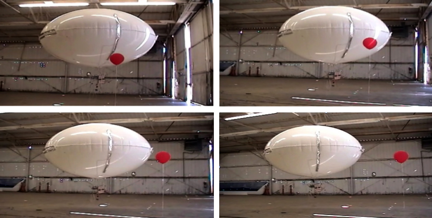
In June 2003, LTAS rented a hangar at the Boulder City, NV airport to build and fly the EK-1. Testing the EK-1 was concluded in early August 2003 after demonstrating the technology to National Institute for Discovery Science (NIDS) board members.
Based on the EK-1 design, a full-scale EK airship would have a rigid, aeroshell comprised largely of LTAS MK-4 lithographic integrated thruster / structure hull panels. As with other contemporary Walden / LTAS airship designs, the MK-4 panel airship likely would have implemented density controlled buoyancy (DCB) active aerostatic lift control and would have had a thin film solar array on the top of the aeroshell.
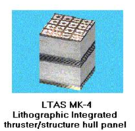
Source: Walden Aerospace
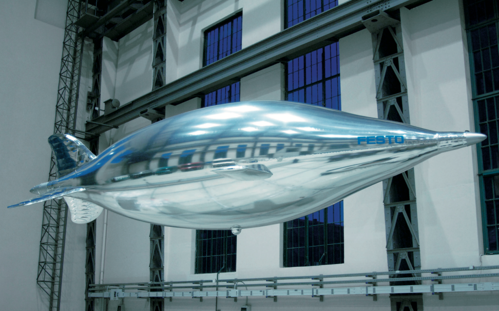
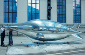
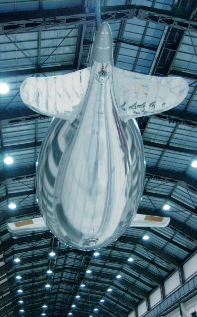
5. The third free-flying, ion-propelled, lighter-than-air craft flew in 2005: the Festo b-IONIC Airfish
The Festo b-IONIC Airfish airship was developed at the Technical University of Berlinwith guidance of the firm Festo AG & Co. KG. This small, non-rigid airship is notable because, in 2005, it became the first aircraft to fly with a solid state propulsion system. The neutrally-buoyant Airfish only flew indoors, in a controlled environment, at a very slow speed, but it flew.
Some of the technical characteristics of the Airfish are listed below:
- Length: 7.5 meters (24.6 ft)
- Span: 3.0 meters (9.8 ft)
- Shell diameter: 1.83 meters (6 ft)
- Helium volume: 9.0 m3(318 ft3)
- Total weight: 9.04 kg (19.9 lb)
- Power source in tail: 12 x 1,500 mAh lithium-ion polymer cells (18 Ah total)
- Power source per wing (two wings): 9 x 3,200 mAh lithium-ion polymer cells (28.8 Ah total)
- High voltage: 20,000 to 30,000 volts
- Buoyancy: 9.0 – 9.3 kg (19.8 – 20.5 lb)
- Total thrust: 8 – 10 grams (0.018 – 0.022 pounds)
- Maximum velocity: 0.7 meters/sec (2.5 kph; 1.6 mph)
The b-IONIC Airfish employed two solid state propulsion systems, an electrostatic ionic jet and a plasma ray, which Festo describes as follows:
- Electrostatic ionic jet: “At the tail end Airfish uses the classic principle of an electrostatic ionic jet propulsion engine. High-voltage DC-fields (20-30 kV) along thin copper wires tear electrons away from air molecules. The positive ions thus created are then accelerated towards the negatively charged counter electrodes (ring-shaped aluminum foils) at high speeds (300-400 m/s), pulling along additional neutral air molecules. This creates an effective ion stream with speeds of up to 10 m/s.”
- Plasma-ray: “The side wings of Airfish are equipped with a new bionic plasma-ray propulsion system, which mimics the wing based stroke principle used by birds, such as penguins, without actually applying movable mechanical parts. As is the case with the natural role model, the plasma-ray system accelerates air in a wavelike pattern while it is moving across the wings.”
The Festo b-IONIC Airfish demonstrated that a solid state propulsion system was possible. The tests also demonstrated that the solid state propulsion systems also reduced drag, raising the intriguing possibility that it may be possible to significantly reduce drag if an entire vessel could be enclosed in a ionized plasma bubble.You’ll find more information on the Festo b-IONIC Airfish, its solid state propulsion system and implications for drag reduction in the the Festo brochure here: https://www.festo.com/net/SupportPortal/Files/344798/b_IONIC_Airfish_en.pdf
You can watch a 2005 short video on the Festo b-IONIC Airfish flight here:
6. NASA ionic wind study – 2009
A corona discharge device generates an ionic wind, and thrust, when a high voltage corona discharge is struck between sharply pointed electrodes and larger radius ground electrodes.
In 2009, National Aeronautics & Space Administration (NASA) researchers Jack Wilson, Hugh Perkins and William Thompson conducted a study to examine whether the thrust of corona discharge systems could be scaled to values of interest for aircraft propulsion. Their results are reported in report NASA/TM-2009-215822, which you’ll find at the following link: https://ntrs.nasa.gov/archive/nasa/casi.ntrs.nasa.gov/20100000021.pdf
Key points of the study included:
- Different types of high voltage electrodes were tried, including wires, knife-edges, and arrays of pins. A pin array was found to be optimum.
- Parametric experiments, and theory, showed that the thrust per unit power could be raised from early values of 5 N/kW to values approaching 50 N/kW, but only by lowering the thrust produced, and raising the voltage applied.
- In addition to using DC voltage, pulsed excitation, with and without a DC bias, was examined. The results were inconclusive as to whether this was advantageous.
- It was concluded that the use of a corona discharge for aircraft propulsion did not seem very practical.”
7. The first heavier-than-air, fixed-wing, ion-propelled aircraft flew in 2018
On 21 November 2018, MIT researchers reported successfully flying the world’s first heavier-than-air, fixed-wing, ion-propelled (electroaerodynamic, EAD) aircraft. You can read the paper by Haofeng Xu, et al., “Flight of an aeroplane with solid-state propulsion,” on the Nature website here: https://www.nature.com/articles/s41586-018-0707-9
The design of the MIT EAD aircraft is shown below:
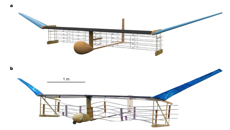
b, Photograph of actual EAD airplane (after multiple flight trials).
Some of the technical characteristics of this MIT aircraft are listed below:
- Wingspan: 4.9 meters (16 ft)
- Total weight: 2.45 kg (5.4 lb)
- Power source: powered by 54 x 3.7 volt 150 mAh lithium-ion polymer cells (8.1 Ah total)
- High voltage: 40,000 volts (+ 20,000 volts / – 20,000 volts)
- Total thrust: 3.2 N, 326 grams (0.718 pounds)
- Maximum velocity: 4.8 meters/sec (17.3 kph; 10.7 mph)
In their paper, the MIT researchers reported:
- “We performed ten flights with the full-scale experimental aircraft at the MIT Johnson Indoor Track…. Owing to the limited length of the indoor space (60 m), we used a bungeed launch system to accelerate the aircraft from stationary to a steady flight velocity of 5 meters/sec within 5 meters, and performed free flight in the remaining 55 meters of flight space. We also performed ten unpowered glides with the thrusters turned off, in which the airplane flew for less than 10 meters. We used cameras and a computer vision algorithm to track the aircraft position and determine the flight trajectory.”
- “All flights gained height over the 8–9 second segment of steady flight, which covered a distance of 40–45 meters…. The average physical height gain of all flights was 0.47 meters…. However, for some of the flights, the aircraft velocity decreased during the flight. An adjustment for this loss of kinetic energy…. results in an energy equivalent height gain, which is the height gain that would have been achieved had the velocity remained constant. This was positive for seven of the ten flights, showing that better than steady-level flight had been achieved in those cases.”
- “In this proof of concept for this method of propulsion, the realized thrust-to-power ratio was 5 N/kW1, which is of the order of conventional airplane propulsion methods such as the jet engine.” Overall efficiency was estimated to be 2.56%.
The propulsion principles of the MIT EAD aircraft are explained in relation to the following diagram in the November 2018 article by Franck Plouraboué, “Flying With Ionic Wind,” which you can read on the Nature website at the following link: https://www.nature.com/articles/d41586-018-07411-z
The following diagram and explanatory text are reproduced from that article.
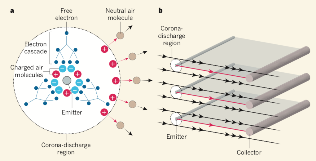
- In Figure a, above: …an electric field (not shown) is applied to the region surrounding a fine wire called the emitter (shown in cross-section). The field induces electron cascades, whereby free electrons collide with air molecules (not shown in the cascades) and consequently free up more electrons. This process produces charged air molecules in the vicinity of the emitter — a corona discharge. Depending on the electric field, negatively or positively charged molecules drift away (red arrows) from the emitter. These molecules collide with neutral air molecules, generating an ionic wind (black arrows).
- In Figure b, above: The aircraft uses a series of emitters and devices called collectors, the longitudinal directions of which are perpendicular to the ionic wind. The flow of charged air molecules occurs mainly along the directions (red arrows) joining emitters and collectors. Consequently, the ionic wind is accelerated (black arrows) predominantly in these regions.
You can view a short video of the MIT EAD aircraft test flights here:
8. The future of ionic propulsion for aerospace applications.
If it can be successfully developed to much larger scales, ionic propulsion offers the potential for aircraft to fly in the atmosphere on a variety of practical missions using only ionized air for propulsion. Using other ionized fluid media, ionic propulsion could develop into a means to fly directly from the surface of the earth into the vacuum of space and then operate in that environment. The following organizations have been developing such systems.
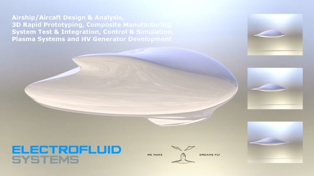
Electrofluidsystems Ltd.
In 2006, the Technical University of Berlin’s Airfish project manager, Berkant Göksel, founded the firm Electrofluidsystems Ltd., which in 2012 was rebranded as IB Göksel Electrofluidsystems. This firm presently is developing a new third generation of plasma-driven airships with highly reduced ozone and nitrogen oxide (NOx) emissions, magneto-plasma actuators for plasma flow control, and the company’s own blended wing type flying wing products. You’ll find their website here: https://www.electrofluidsystems.com
MIT researchers are developing designs for high-performance aircraft using ionic propulsion. Theoretically, efficiency improves with speed, with an efficiency of 50% possible at a speed of about 1,000 kph (621 mph). You can watch a short video on MIT work to develop a Star Trek-like ion drive aircraft here:
University of Florida, Applied Physics Research Group
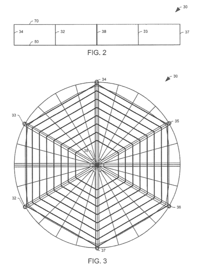
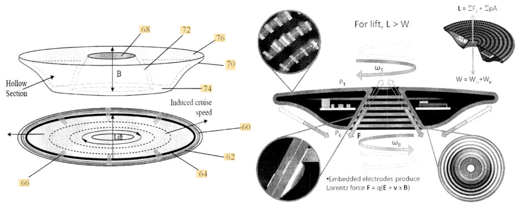
In the early 2000s, a Wingless Electromagnetic Air Vehicle (WEAV) was invented by Dr. Subrata Roy, a plasma physicist and aerospace engineering professor at the University of Florida. WEAV is described as a heavier-than-air flight system that can self-lift, hover, and fly using plasma propulsion with no moving components. The laboratory-scale device is six inch (15.2 cm) in diameter. The basic configuration of the disc-shaped craft is shown in patent 8960595B2 Figure 1.
This research project has been supported by the US Air Force Office of Scientific Research. You’ll find details on WEAV technology in the University of Florida’s 2011 final report at the following (very slow loading) link: https://apps.dtic.mil/dtic/tr/fulltext/u2/a564120.pdf
In this report, the authors describe the technology: “This revolutionary concept is based on the use of an electro-(or magneto) hydrodynamic (EHD/MHD) thrust generation surface that is coated with multiple layers of dielectric polymers with exposed and/or embedded electrodes for propulsion and dynamic control. This technology has the unique capability of imparting an accurate amount of thrust into the surrounding fluid enabling the vehicle to move and react. Thrust is instantaneously and accurately controlled by the applied power, its waveform, duty cycle, phase lag and other electrical parameters. Once the applied power is removed the thrust vanishes.”
The following patents related to WEAV technology have been filed and assigned to the University of Florida Research Foundation Inc.:
- Patent US8382029B2, “Wingless hovering of micro air vehicle”, filed 23 December 2008, granted 26 February 2013: https://patents.google.com/patent/US8382029B2/en?oq=8382029
- Patent US 8960595B2, “Wingless hovering of micro air vehicle”, filed 19 December 2012, granted 24 February 2015: https://patents.google.com/patent/US8960595?oq=8960595
- Patent EP2046640A1, “Wingless Hovering of Micro Air Vehicle (WHOMAV),” filed 31 July 2007, granted on Oct 12, 2011: https://patents.google.com/patent/EP2046640B1/en?oq=EP2046640
- Patent WO 2008/016928, “Wingless Hovering of Micro Air Vehicle,” filed 31 July 2007, published 7 February 2008: https://patents.google.com/patent/WO2008016928A1/en?oq=•WO+2008%2f016928
These patents do not cite Alexander de Seversky’s Patent 3130945, “Ionocraft.”
9. More reading on electrodynamic propulsion for aircraft
General
- Kevin Dupzyk, “The Long, Strange History of the Electric Wind,” Popular Mechanics, 5 December 2018, https://www.popularmechanics.com/flight/g25397392/electric-wind-ionic-wind-history/
- M. Robinson, “Movement of Air in the Electric Wind of the Corona Discharge:, Technical Paper TP60-2, Research-Cottrell, Inc., Bound Brook, NJ, 8 June 1960; https://apps.dtic.mil/dtic/tr/fulltext/u2/262830.pdf
- Derek Dunn-Rankin, “Characterization of Ionic Wind from Flames and Corona Discharges,” Mechanical and Aerospace Engineering, University of California, Irvine, 25 February 2005; http://mae2.eng.uci.edu/~ddunnran/presentations_pub/caltech_05.pdf
- Berkant Göksel & Igor Mashek, “First Breakthrough for Future Air-Breathing Magneto-Plasma Propulsion Systems:, Journal of Physics Conference Series 825(1), September 2016; https://www.researchgate.net/publication/308107457_First_Breakthrough_for_Future_Air-Breathing_Magneto-Plasma_Propulsion_Systems
- P. Zheng, et al., “A Comprehensive Review of Atmospheric-Breathing Electric Propulsion Systems,” International Journal of Aerospace Engineering, Article ID 8811847, 7 October 2020; https://www.hindawi.com/journals/ijae/2020/8811847/
- “Propulsion Systems,” Instituto de Technologias Sustentáves Nikola Tesla, Brazilia, Brazil website: http://www.institutotesla.org/propulsion.html
MIT electroaerodynamic aircraft
- Haofeng Xu, et al., “Flight of an aeroplane with solid-state propulsion,” Nature, Volume 563, pp 532–535 (2018); https://www.nature.com/articles/s41586-018-0707-9?WT.feed_name=subjects_aerospace-engineering
- Nicolas Monrolin, Franck Plouraboué, Olivier Praud.“Electrohydrodynamic Thrust for In-Atmosphere Propulsion,” AIAA Journal, American Institute of Aeronautics and Astronautics, 2017, vol. 55 (n° 12), pp. 4296-4305. 10.2514/1.J055928 . hal-01660600; https://hal.archives-ouvertes.fr/hal-01660600/document
- Plouraboué, Franck, “Flying with ionic wind,” 2018, Nature, 563, pp 476-477, ISSN 0028-0836; https://www.nature.com/articles/d41586-018-07411-z
- Anna Demming, “Combustion-free propeller-free aeroplane takes flight,” Physics Worls, 21 November 2019; https://physicsworld.com/a/combustion-free-propeller-free-aeroplane-takes-flight/
Ionocraft lifters
- Xavier Borg, “Full analysis & design solutions for EHD Thrusters at saturated corona current conditions Category: Ionocrafts & Lifters,” 1 January 2006; https://www.gsjournal.net/h/papers_download.php?id=1830
- Daniel Drew, “The Ionocraft: Flying Microrobots With No Moving Parts,” Technical Report No. UCB/EECS-2018-164, Electrical Engineering and Computer Sciences, University of California at Berkeley, 10 December 2018; https://www2.eecs.berkeley.edu/Pubs/TechRpts/2018/EECS-2018-164.pdf
WEAV
- Subrata Roy, et al., “Demonstration of a Wingless Electromagnetic Air Vehicle,” Final Report AFRL-OSR-VA-TR-2012-0922, University of Florida, Applied Physics Research Group: https://apps.dtic.mil/dtic/tr/fulltext/u2/a564120.pdf
- Larry Greenemeir, “The World’s First Flying Saucer: Made Right Here on Earth,” Scientific American, 7 July 2008: https://www.scientificamerican.com/article/worlds-first-flying-saucer/
- “Wingless Electromagnetic Air Vehicle,” Wikipedia: https://en.m.wikipedia.org/wiki/Wingless_Electromagnetic_Air_Vehicle

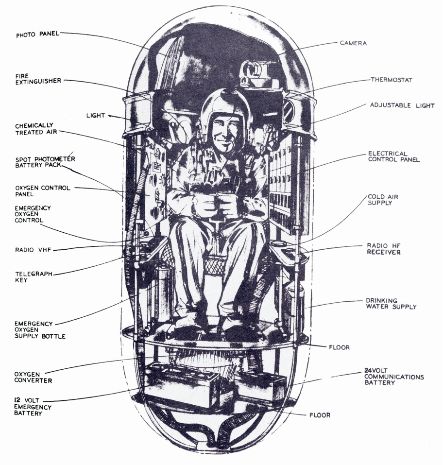
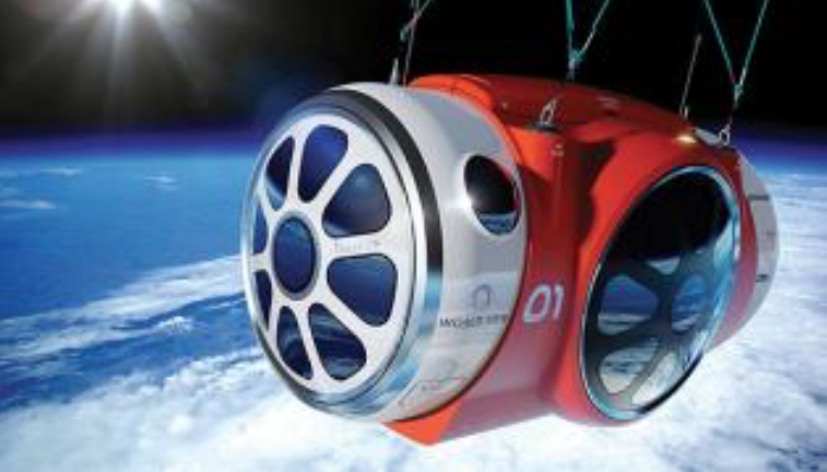
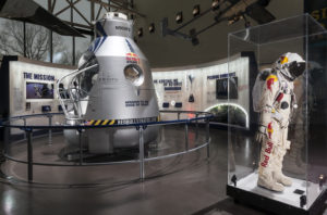 Red Bull Stratos gondola & pressure suit. Source: Smithsonian