National Submarine Day, which occurs each year on 11 April, honors the anniversary of the day in 1900 when the U.S. Navy acquired the Holland VI submarine, which has been generally recognized as the world’s first modern submarine.
Similar, though slightly larger variants of the original Holland VI design also were acquired by the UK (1901 – 1904) and Japan (1904).
2. The Holland VI and the original U.S. Holland-class submarines
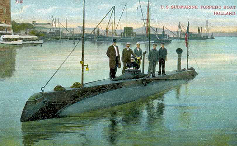
Designed in 1896 by Irish-American inventor John Phillip Holland and his Holland Torpedo Boat Company, the Holland VI was built at the Crescent Shipyard in Elizabeth, New Jersey, where Arthur Leopold Busch was the chief constructor / naval architect. The Holland VI was launched on 17 May 1897. This diminutive submarine (by today’s standards) had an overall length of 53 ft 10 in (16.41 m), displacements of 65 tons surfaced / 75 tons submerged, and was operated by a crew of six.
Picture post card of the USS Holland (SS-1). Source: Universal Ship Cancellation Society (USCS #3608)
The Holland VI brought together a host of impressive features for the first time in one vessel, including:
Efficient hydrodynamic hull shape [teardrop-shape with bulbous bow and tapered stern] with good seakeeping ability on the open ocean.
Separate main and auxiliary ballast systems enable rapid diving and surfacing with minimial changes to the longitudinal center of gravity while underway.
Accomplished by operating with full or nearly full ballast tanks when submerged.
Allowed precise control of trim angle while submerged.
Able to dive to and accurately maintain a significant depth [up of 75 feet (23 m)].
Diving planes provide the means to precisely control depth [stern planes only, located behind the propeller].
Dual propulsion systems driving a single propeller at the stern.
Internal combustion engine provides reliable power on the surface, enabling long transits while charging the batteries [up to 200 nautical miles (370 km) at 6 knots]
Lead-acid storage batteries provide power to run submerged for a considerable distance [about 30 nautical miles (56 km) at 5.5 knots].
Conning tower for directing ship and weapons activities on the surface or semi-submerged.
No periscope. View ports around the top of the conning tower provided the commander with intermittent views while “porpoising” semi-submerged near the surface.
Offensive weapons systems.
One reloadable torpedo tube at the bow, with three self-propelled torpedoes carried internally.
One pneumatic dynamite gun at the bow that, on the surface, fired large projectiles, sometimes called “aerial torpedoes.” [This was subsequently removed].
John P. Holland first demonstrated the Holland VI to the U.S. Navy on 17 March 1898. It appears that Submarine Day originally was celebrated to mark anniversaries of this date.
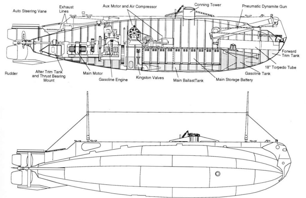
USS Holland (SS-1) internal and external arrangements. The interior space was one contiguous compartment. Source: Navsource.com
The U.S. Navy purchased the Holland VI for $150,000 on 11 April 1900. The Navy renamed and commissioned the submarine as the USS Holland on 12 October 1900. While the Navy previously owned and operated two submarines, Alligator (1862 – 63) and Intelligent Whale (1869 – 73), the USS Holland was the first commissioned submarine in the fleet. Lieutenant H.H. Caldwell became the first commanding officer of a modern commissioned submarine.
On 25 August 1905, the USS Holland made history by being the first American submarine to carry a U.S. President, Theodore Roosevelt, while she ran submerged for 55 minutes.The Navy ordered six more Holland-class submarines from the Electric Boat Company, which was founded in 1899 and had acquired the Holland Torpedo Boat Company and the continuing services of John P. Holland as Manager. Patent US702729 was granted on 17 June 1902 for Holland’s submarine design and assigned to Electric Boat Company.
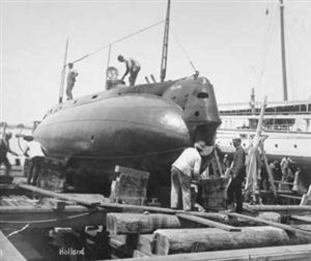
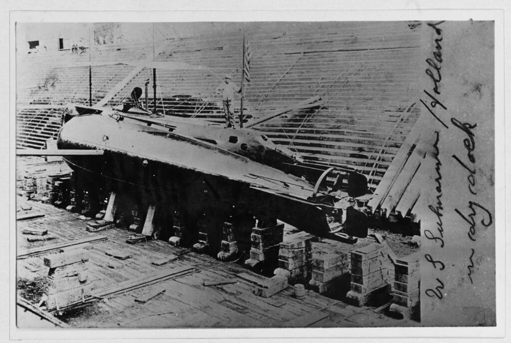
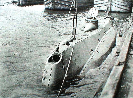
Bow quarter view of USS Holland (SS-1) in drydock. Source: Naval Institute photo archiveStern quarter view of USS Holland (SS-1) in drydock. Source: Naval History and Heritage CommandBow view of USS Holland (SS-1) dockside showing the muzzle of the pneumatic dynamite gun at the bow and the open conning tower amidships. Source: Scientific American 1898 via Wikimedia Commons
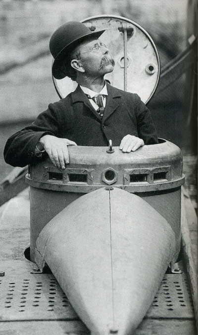
John Philip Holland in the conning tower. Note the viewing ports around the top rim of the tower. Source: Wikimedia Commons
Reenactment showing the interior of the conning tower. Source: screenshot from “Submarine #1” video (2022)
The U.S. Navy’s Holland-class subs rapidly became obsolete as submarine technology advanced. USS Holland finished out her naval career in Norfolk, VA, was stricken from the Navy Register of Ships on 21 November 1910, and was sold for scrap in 1913. The USS Holland did not receive its “SS-1” designation until the Navy’s modern hull classification system was instituted on 17 July 1920.
3. The UK Holland-class submarines
In their online history, BAE Systems reports, “Following meetings with the Admiralty, an agreement was made on 27th October 1900 between the Electric Boat Company and Vickers Sons & Maxim Ltd of Barrow-in-Furness, giving Vickers 25-year license to manufacture the Holland-class of submarines, using Electric Boats patents.”
Vickers built five Holland-class subs for the Royal Navy. These were somewhat larger than their U.S. counterparts, with a length of 63 ft 4 in (19.3 m), a submerged displacement of 107 tons and a crew of eight.
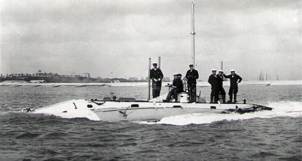
HMS Holland 1 underway. Source: RN Submarine Museum via Wikipedia
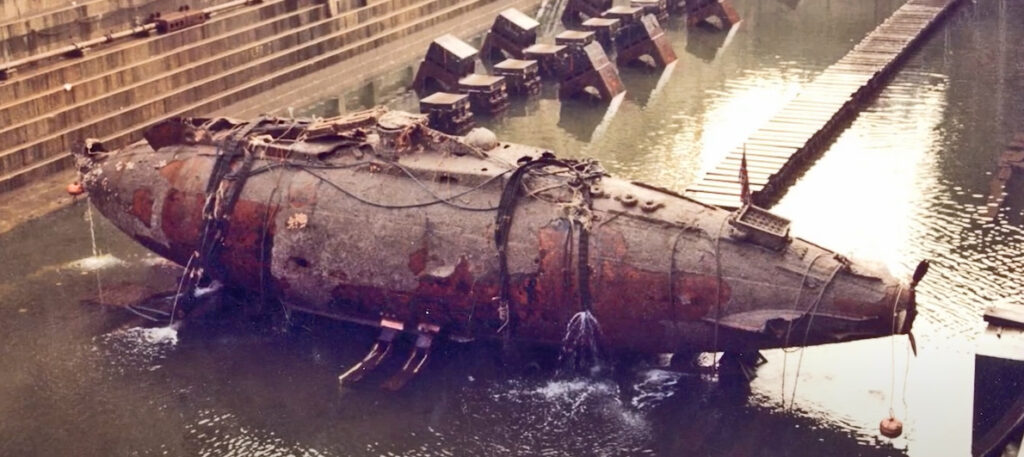
The first sub, designated Holland 1, was launched in 1901. After 12 years of service, it was decommissioned in 1913 and sank at sea while under tow near Plymouth, on its way to be scrapped. The location of the sunken sub was discovered in 1981 and the largely intact vessel was raised in 1983. Today, the Holland 1 is on display at the Royal Navy’s Submarine Museum in Gosport, UK, in a climate-controlled environment designed to arrest further corrosion.
UK’s Holland 1 in a drydock after being recovered from the seabed in 1983. Source: screenshot from The National Museum of the Royal Navy video (2022)
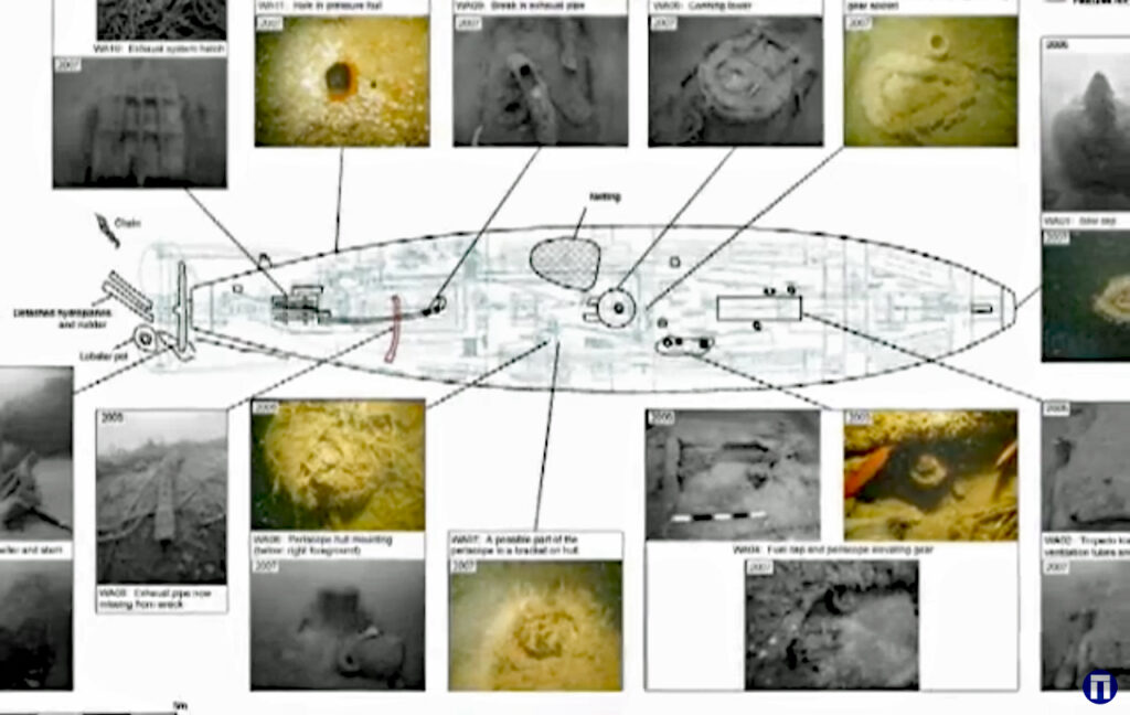
The last of the UK’s Holland-class submarines, Holland 5, was launched in 1904. After eight years in service, Holland 5 sank off the coast of Sussex in 1912 while being towed for decommissioning. In 1985, the intact, but encrusted, submarine was located on the seabed at a depth of 35 meters (115 ft), where it remains today, subject to the Protection of Wrecks Act 1973.
Map of the UK’s HMS Holland 5 on the seabed. Source: screenshot from Wessex Archaeology video (2010)
4. The Japanese Holland-class submarines
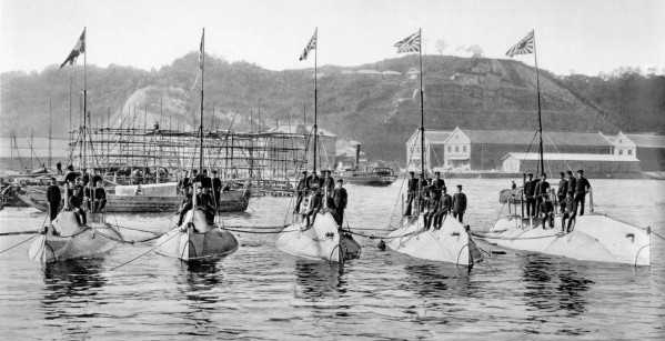
Japanese representatives had sailed aboard Holland IV during early testing in 1898 and during trials on the Potomac River in 1900. During the Russo-Japanese War, the Japanese government purchased five “improved” Holland-class submarines from the Electric Boat Company in great secrecy, since the U.S. was a “neutral” nation. These submarines had a length of 67 ft (20.4 m) and a submerged displacement of 126 tons. They were delivered to Japan partially assembled in December 1904. Assembly was completed at the Yokosuka Naval Arsenal, the crews were trained, and the submarines were ready for combat operations in August 1905. None saw action before the war ended in September 1905. They served as training boats until being retired from service 1920.
Japan’s first submarine squadron consisted of five “improved” Holland-class (Type 7-P) subs. Source: Dynamic America, edited by J. Niven, 1960, via Gary McCue
5. Comparison with today’s nuclear-powered submarines
Since the first production run of Holland-class submarines built for the U.S. Navy, Electric Boat Company (now General Dynamics Electric Boat) has been delivering submarines to the Navy for more than 120 years.
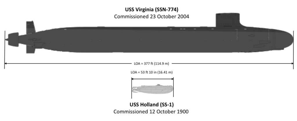
The Navy’s Virginia-class SSNs, which started entering the fleet in 2004 with USS Virginia(SSN-774), are 7,800 ton behemoths in comparison to the USS Holland.
Comparison of USS Holland (SS-1) & USS Virginia (SSN-774) Sources: composite adapted from Wikiwand (SSN-774) & Navsource (SS-1)
Almost 20 years later, the latest Virginia-class Block V SSNs are even bigger, with an overall length of 460 ft (140 m) and a submerged displacement of over 10,000 tons. The largest submarines currently in the Navy’s fleet are the aging Ohio-class SSBNs (strategic missile submarines) and SSGNs (cruise missile submarines). With an overall length of 560 ft (170 m) and a submerged displacement of about 18,750 tons, the Ohio-class subs dwarf all the other U.S. subs.
Since 2018, the U.S. Navy has been testing a large, autonomous, unmanned underwater vehicle (UUV), Echo Voyager, which is 51 feet (15.5 meters) long and has a displacement of about 50 tons. This is approximately the same size as the USS Holland (SS-1).
John P. Holland would be amazed at the progress made in submarine design and operation over the 123 years since the USS Holland was acquired by the U.S. Navy in 1990 and commissioned that same year.
Enjoy National Submarine Day on 11 April, and remember that, in the U.S., it’s pronounced “sub-marine-er,” not “sub-mariner,” as they say in the UK and in Marvel Comics. If you’re going to dress up for the occasion, may I suggest this stylish T-shirt.
“Navy Virginia (SSN-774) Class Attack Submarine Procurement: Background and Issues for Congress,” Congressional Research Service report RL32418, updated 21 December 2022: https://sgp.fas.org/crs/weapons/RL32418.pdf
“Navy Large Unmanned Surface and Undersea Vehicles: Background and Issues for Congress,” Congressional Research Service report R45757, updated 21 December 2022: https://sgp.fas.org/crs/weapons/R45757.pdf
“‘No Deck to Strut Upon’ 1971 U.S. Navy Film, John P. Holland and Development of the Submarine, 80114,” (28.06 min), Periscope Films, posted online 7 June 2022: https://www.youtube.com/watch?v=mVzhn3X93Hg
“The Royal Navy’s first submarine, Holland 1, turns 120 years old in 2021,” (2:56 min), posted by The National Museum of the Royal Navy, 27 September 2021:https://www.youtube.com/watch?v=KgzHUFc4aQM
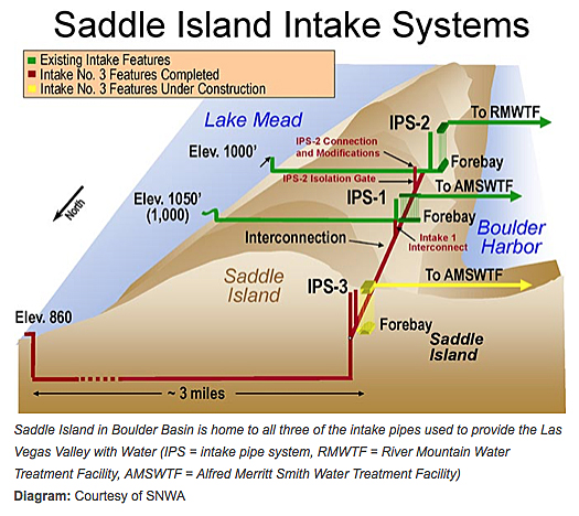
Las Vegas relies on Lake Mead for 90% of its water needs. Currently, water from Lake Mead can be supplied to Las Vegas by three intakes at different levels in the lake. The newest, and deepest, is known as the “third straw” intake (IPS-3), which taps into the lake at 860 feet above sea level. That’s 190 feet below the highest existing intake, IPS-1, at 1,050 feet.
The operation of this three-intake system is explained in Southern Nevada Water Authority’s (SNWA) short video, “How does the SNWA’s Low Lake Level Pumping Station protect our drinking water supply?” at the following link: https://www.youtube.com/watch?v=bDDuid6XJnw&t=39s
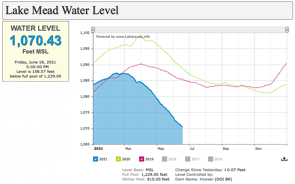
On 18 June 2021, the lake level was 1,070.43 feet MSL at 5:00 PM. This is 158.57 feet below the “full pool” level of 1,229.00 feet and is only 20.43 feet above the highest (IPS-1) intake.
On 10 June 2021, Lake Mead water level was 1,071.51 at 7:00 AM and was about 36% full. The lake had not been this low since July 2016. Using just the 10 June and 18 June data points, lake water level currently is decreasing at about 1.5 inches per day.
Runoff from the Rocky Mountain snowpack is essentially over this year, so water level is expected to continue declining until the start of the next rainy season in November.
The first-ever official federal water shortage declaration is expected in August 2021, when the Bureau of Reclamation issues its regularly scheduled long-term water level projection. A Level 1 declaration would be implemented in January 2022 under agreements negotiated with seven states that rely on Colorado River water: Arizona, California, Colorado, Nevada, New Mexico, Utah and Wyoming. Water from the Colorado River serves 40 million people in these states and Mexico.
Let’s pray for a lot of wet weather in the US southwest.
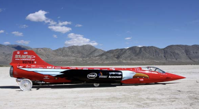
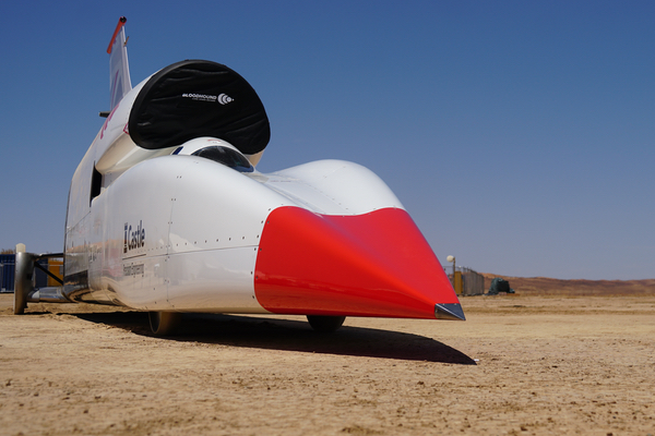
I’ve reported previously on the Bloodhound LSR (land speed record) car in 2015, 2017, and lastly in 2019 when driver Andy Green made a series of high-speed test runs on the Hakskeen Pan in the Kalahari Desert in South Africa. On 17 November 2019, he achieved a top speed run at 628 mph (1,010 kph). The primary goal of the 2019 test campaign was to validate vehicle design and operation during high-speed runs up to 621 mph (1,000 kph). To that, the team responded, “Mission accomplished.” You can read my post on the Bloodhound LSR’s 2019 campaign here: https://lynceans.org/all-posts/land-speed-record-lows-and-highs-in-2019/
The 2019 test runs also were intended to provide an opportunity to fine-tune Bloodhound LSR before attempting a world land speed record run in 2020. However, lack of funds in 2020 deferred installing the Nammo rocket engine needed for the land speed record attempt. The worldwide COVID pandemic further intervened, cancelling a record attempt in 2020 and 2021.
The owner, Ian Warhurst, who had previously rescued the Bloodhound LSR from insolvency and then funded the 2019 high-speed tests, put the vehicle up for sale in January 2021. On 17 May 2021, the Bloodhound LSR team and the Coventry Transport Museum in Coventry, UK, announced the Bloodhound LSR jet car had moved into a new home in the museum where it is now on public display as part of the Biffa Award Land Speed Record Exhibition.
The Bloodhound LSR team reported, “….the sponsorship team are busy raising the funding required to attempt a new world land speed record, with a speed above 800mph. Once the required funding and investment has been raised, Bloodhound will leave the museum and be prepared for the record-breaking campaign.”
Bloodhound LSR on display at the Coventry Transport Museum Source: Bloodhound LSR
In the Biffa Award Land Speed Record Exhibition at the Coventry Transport Museum, Bloodhound LSR joins two UK world land speed record holders: Thrust2 and ThrustSSC.
On 4 October 1983, Richard Noble drove the Thrust2 to a world land speed record two-way average speed of 633.468 mph (1,019.468 kph) in the Black Rock Desert in Nevada, USA.
Thrust2 on display at the Coventry Transport Museum. Source: AJB83 at English Wikipedia
On 15 October 1997, Andy Green drove the ThrustSSC to a new land speed record and broke the sound barrier with a speed of 763mph (Mach 1.020, 1,228 kph) in the Black Rock Desert. This occurred 50 years after Captain “Chuck” Yeager, flying the Bell X-1 rocket-powered aircraft, made the first supersonic flight on 14 October 1947.
ThrustSSC on display at the Coventry Transport Museum Source: CTM via Vauxford (CC BY-SA 4.0)
Festo is a German multinational industrial control and automation company based in Esslingen am Neckar, near Stuttgart. The Festo website is here: https://www.festo.com/group/en/cms/10054.htm
Festo reports that they invest about 8% of their revenues in research and development. Festo’s draws inspiration for some of its control and automation technology products from the natural world. To help facilitate this, Festo established the Bionic Learning Network, which is a research network linking Festo to universities, institutes, development companies and private inventors. A key goal of this network is to learn from nature and develop “new insights for technology and industrial applications”…. “in various fields, from safe automation and intelligent mechatronic solutions up to new drive and handling technologies, energy efficiency and lightweight construction.”
One of the challenges taken on by the Bionic Learning Network was to decipher how birds fly and then develop robotic devices that can implement that knowledge and fly like a bird. Their first product was the 2011 SmartBird and their newest product is the 2020 BionicSwift. In this article we’ll take a look at these two bionic birds and the significant advancements that Festo has made in just nine years.
2. SmartBird
On 24 March 2011, Festo issued a press release introducing their SmartBird flying bionic robot, which was one of their 2011 Bionic Learning Network projects. Festo reported:
“The research team from the family enterprise Festo has now, in 2011, succeeded in unraveling the mystery of bird flight. The key to its understanding is a unique movement that distinguishes SmartBird from all previous mechanical flapping wing constructions and allows the ultra-lightweight, powerful flight model to take off, fly and land autonomously.”
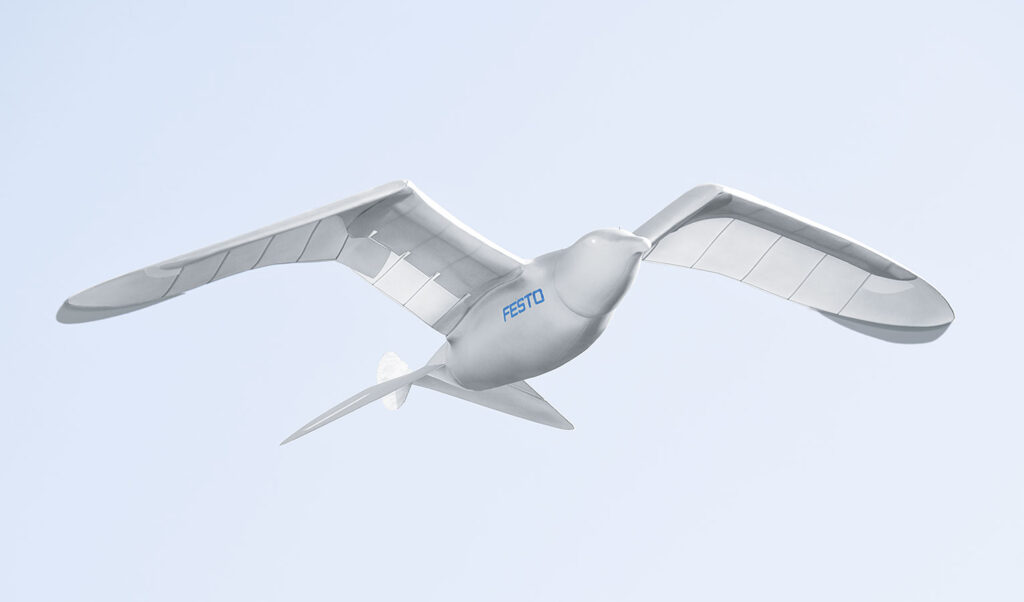
“SmartBird flies, glides and sails through the air just like its natural model – the Herring Gull – with no additional drive mechanism. Its wings not only beat up and down, but also twist at specific angles. This is made possible by an active articulated torsional drive unit, which in combination with a complex control system makes for unprecedented efficiency in flight operation. Festo has thus succeeded for the first time in attaining an energy-efficient technical adaptation of this model from nature.”
SmartBird measures 1.07 meters (42 in) long with a wingspan of 2.0 meters (79 in) and a weigh of 450 grams (16 ounces, 1 pound). This is about a 1.6X scale-up in the length and span of an actual Herring Gull, but at about one-third the weight. It is capable of autonomous takeoff, flight, and landing using just its wings, and it controls itself the same way birds do, by twisting its body, wings, and tail. SmartBird’s propulsion system has a power requirement of 23 watts.
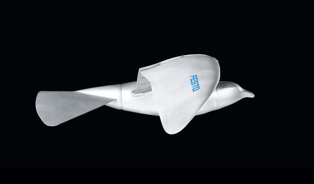
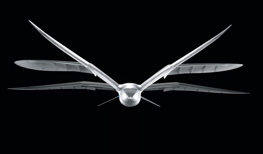
On 1 July 2020, Festo introduced the BionicSwift as their latest ultra light flying bionic robot that mimics how actual birds fly.
The BionicSwift, inspired by a Common Swift, measures 44.5 cm (17.5 in) long with a wingspan of 68 cm (26.7 in) and a weight of just 42 grams (1.5 ounces). It’s approximately a 2X scale-up of a Common Swift, but still a remarkably compact, yet complex flying machine with aerodynamic plumage that closely replicates the flight feathers on an actual Swift. The 2011 SmartBird was more than twice the physical size and ten times heavier.
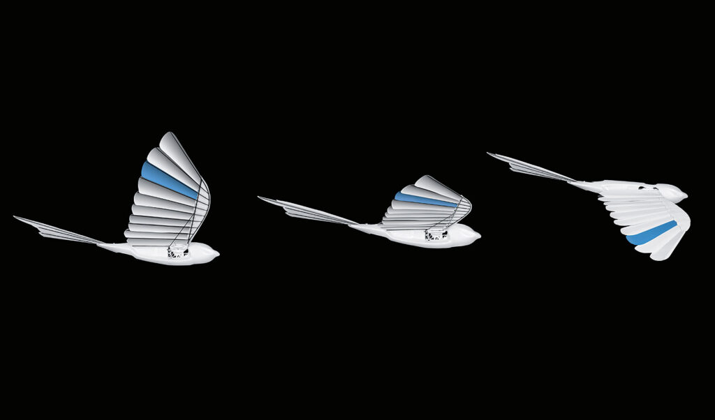
The BionicSwift is agile, nimble and can even fly loops and tight turns. Festo reports: “Due to this close-to-nature replica of the wings, the BionicSwifts have a better flight profile than previous wing-beating drives.” Compare the complex, feathered wing structure in the following Festo photos of the BionicSwift with the previous photos showing the simpler, solid wing structure of the 2011 SmartBird.
Source: All three BionicSwift photos from Festo
A BionicSwift can fly singly or in coordinated flight with a group of other BionicSwifts. Festo describes how this works: “Radio-based indoor GPS with ultra wideband technology (UWB) enables the coordinated and safe flying of the BionicSwifts. For this purpose, several radio modules are installed in one room. These anchors then locate each other and define the controlled airspace. Each robotic bird is also equipped with a radio marker. This sends signals to the anchors, which can then locate the exact position of the bird and send the collected data to a central master computer, which acts as a navigation system.” Flying time is about seven minutes per battery charge.
4. For more information about other Festo bionic creations:
I encourage you to visit the Festo BionIc Learning Network webpage at the following link and browse the resources available for the many intriguing projects. https://www.festo.com/group/en/cms/10156.htm
On this webpage you’ll find a series of links listed under the heading “More Projects,” which will introduce you to the wide range of Bionic Learning Network projects since 2006.
You also can watch the following YouTube short videos of Festo’s many bionic creations:
BionicFinWave (2018):replicates the swimming movements of sea creatures with undulating fins to create a unique fin drive system for an autonomous underwater vehicle: https://www.youtube.com/watch?v=fRNq55EbnZc
AirRay (2010): replicates the natural underwater movements of a Manta Ray in a larger-than-life, neutrally buoyant, ray-shaped airship with a flapping wing drive: https://www.youtube.com/watch?v=c3-wIICjAhE
AquaRay (2010): replicates the natural underwater movements of a Manta Ray in a full-size autonomous underwater vehicle with a flapping wing drive: https://www.youtube.com/watch?v=F4-6oNagIvk
AirPenguin (2009): replicates the natural underwater movements of a penguin in a larger-than-life, neutrally buoyant, penguin-shaped airship: https://www.youtube.com/watch?v=jPGgl5VH5go
AquaPenguin (2009): replicates the natural underwater movements of a penguin in a small penguin-sized autonomous underwater vehicle: https://www.youtube.com/watch?v=u8tfES8gImc
AirJelly (2008): replicates the natural underwater movements of a jelly fish in a larger-than-life, neutrally buoyant, jelly fish-shaped airship: https://www.youtube.com/watch?v=divLsTtA5vk
AquaJelly (2008): replicates the natural underwater movements of a jelly fish in a small, autonomous, peristaltic drive autonomous underwater vehicle that can operate in coordination with several other AquaJellies: https://www.youtube.com/watch?v=N-O8-N71Qcw
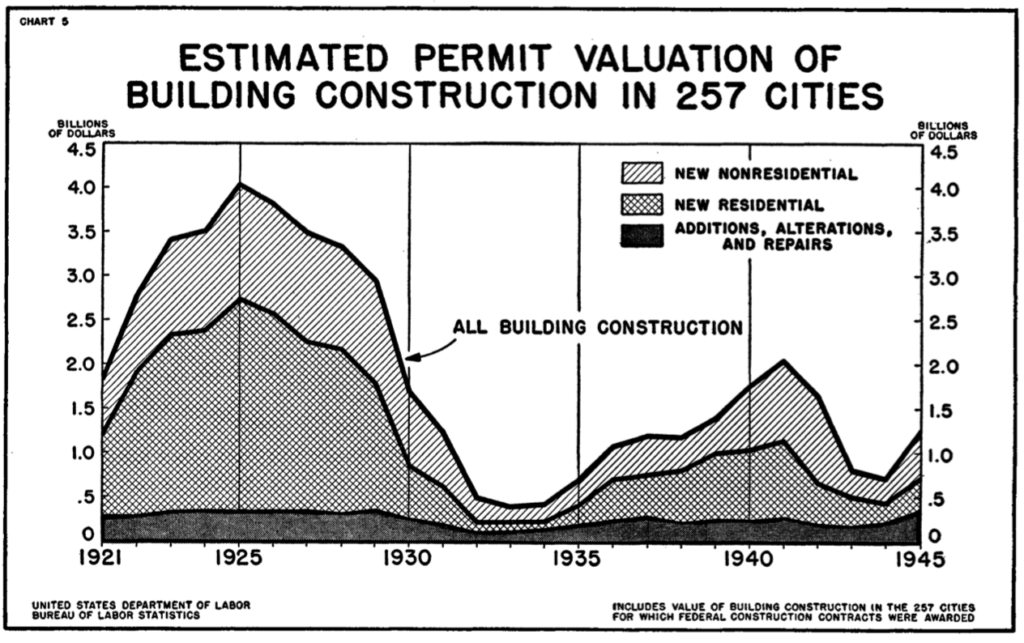
At the start of World War II (WW II), US home ownership had dropped to a low of 43.6% in 1940, largely as a consequence of the Great Depression and the weak US economy in its aftermath. During WW II, the War Production Board issued Conservation Order L-41 on 9 April 1942, placing all construction under rigid control. The order made it necessary for builders to obtain authorization from the War Production Board to begin construction costing more than certain thresholds during any continuous 12-month period. For residential construction, that limit was $500, with higher limits for business and agricultural construction. The impact of these factors on US residential construction between 1921 and 1945 is evident in the following chart, which shows the steep decline during the Great Depression and again after Order L-41 was issued.
Source: “Construction in the War Years – 1942 -45,” US Department of Labor, Bulletin No. 915
By the end of WW II, the US had an estimated 7.6 million troops overseas. The War Production Board revoked L-41 on 15 October 1945, five months after V-E (Victory in Europe) day on 8 May 1945 and six weeks after WW II ended when Japan formally surrendered on 2 September 1945. In the five months since V-E day, about three million soldiers had already returned to the US. After the war’s end, the US was faced with the impending return of several millions more veterans. Many in this huge group of veterans would be seeking to buy homes in housing markets that were not prepared for their arrival. Within the short span of a year after Order L-41 was revoked, the monthly volume of private housing expenditures increased fivefold. This was just the start of the post-war housing boom in the US.
In a March 1946 Popular Science magazine article entitled “Stopgap Housing,” the author, Hartley Howe, noted, “ Even if 1,200,000 permanent homes are now built every year – and the United States has never built even 1,000,000 in a single year – it will be 10 years before the whole nation is properly housed. Hence, temporary housing is imperative to stop that gap.” To provide some immediate relief, the Federal government made available many thousands of war surplus steel Quonset huts for temporary civilian housing.
Facing a different challenge in the immediate post-war period, many wartime industries had their contracts cut or cancelled and factory production idled. With the decline of military production, the U.S. aircraft industry sought other opportunities for employing their aluminum, steel and plastics fabrication experience in the post-war economy.
2. Post-WW II prefab aluminum and steel houses in the US
In the 2 September 1946 issue of Aviation News magazine, there was an article entitled “Aircraft Industry Will Make Aluminum Houses for Veterans,” that reported the following:
“Two and a half dozen aircraft manufacturers are expected soon to participate in the government’s prefabricated housing program.”
“Aircraft companies will concentrate on FHA (Federal Housing Administration) approved designs in aluminum and its combination with plywood and insulation, while other companies will build prefabs in steel and other materials. Designs will be furnished to the manufacturers.”
“Nearly all war-surplus aluminum sheet has been used up for roofing and siding in urgent building projects; practically none remains for the prefab program. Civilian Production Administration has received from FHA specifications for aluminum sheet and other materials to be manufactured, presumably under priorities. Most aluminum sheet for prefabs will be 12 to 20 gauge – .019 – .051 inch.”
In October 1946, Aviation News magazine reported, “The threatened battle over aluminum for housing, for airplanes and myriad postwar products in 1947 is not taken too seriously by the National Housing Agency, which is negotiating with aircraft companies to build prefabricated aluminum panel homes at an annual rate as high as 500,000.”……”Final approval by NHA engineers of the Lincoln Homes Corp. ‘waffle’ panel (aluminum skins over a honeycomb composite core) is one more step toward the decision by aircraft companies to enter the field.…..Aircraft company output of houses in 1947, if they come near meeting NHA proposals, would be greater than their production of airplanes, now estimated to be less than $1 billion for 1946.”
In late 1946, the FHA Administrator, Wilson Wyatt, suggested that the War Assets Administration (WAA), which was created in January 1946 to dispose of surplus government-owned property and materials, temporarily withhold surplus aircraft factories from lease or sale and give aircraft manufacturers preferred access to surplus wartime factories that could be converted for mass-production of houses. The WAA agreed.
Under the government program, the prefab house manufacturers would have been protected financially with FHA guarantees to cover 90% of costs, including a promise by Reconstruction Finance Corporation (RFC) to purchase any homes not sold.
Many aircraft manufacturers held initial discussions with the FHA, including: Douglas, McDonnell, Martin, Bell, Fairchild, Curtis-Wright, Consolidated-Vultee, North American, Goodyear and Ryan. Boeing did not enter those discussions and Douglas, McDonnell and Ryan exited early. In the end, most aircraft manufacturer were unwilling to commit themselves to the postwar prefab housing program, largely because of their concerns about disrupting their existing aircraft factory infrastructure based on uncertain market estimates of size and duration of the prefab housing market and lack of specific contract proposals from the FHA and NHA.
The original business case for the post-war aluminum and steel pre-fabricated houses was that they could be manufactured rapidly in large quantities and sold profitably at a price that was less than conventional wood-constructed homes. Moreover, the aircraft manufacturing companies restored some of the work volume lost after WW II ended and they were protected against the majority of their financial risk in prefab house manufacturing ventures.
Not surprisingly, building contractors and construction industry unions were against this program to mass-produce prefabricated homes in factories, since this would take business away from the construction industry. In many cities the unions would not allow their members to install prefabricated materials. Further complicating matters, local building codes and zoning ordnances were not necessarily compatible with the planned large-scale deployment of mass-produced, prefabricated homes.
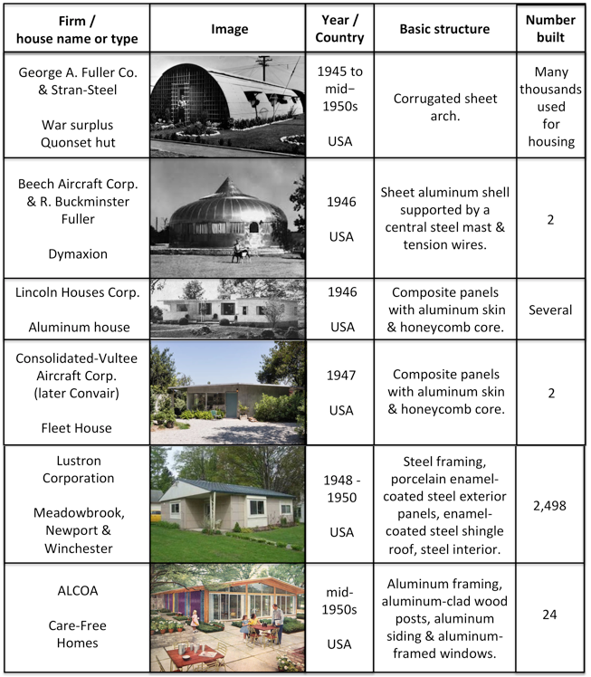
The optimistic prospects for manufacturing and erecting large numbers of prefabricated aluminum and steel homes in post-WW II USA never materialized. Rather than manufacturing hundreds of thousands of homes per year, the following five US manufacturers produced a total of less than 2,600 new aluminum and steel prefabricated houses in the decade following WW II: Beech Aircraft, Lincoln Houses Corp., Consolidated-Vultee, Lustron Corp. and Aluminum Company of America (Alcoa). In contrast, prefabricators offering more conventional houses produced a total of 37,200 units in 1946 and 37,400 in 1947. The market demand was there, but not for aluminum and steel prefabricated houses.
US post-WW II prefabricated aluminum and steel houses
These US manufacturers didn’t play a significant part in helping to solve the post-WW II housing shortage. Nonetheless, these aluminum and steel houses still stand as important examples of affordable houses that, under more favorable circumstances, could be mass-produced even today to help solve the chronic shortages of affordable housing in many urban and suburban areas in the US.
Some of the US post-WW II housing demand was met with stop gap, temporary housing using re-purposed, surplus wartime steel Quonset huts, military barracks, light-frame temporary family dwelling units, portable shelter units, trailers, and “demountable houses,” which were designed to be disassembled, moved and reassembled wherever needed. You can read more about post-WW II stop gap housing in the US in Hartley Howe’s March 1946 article in Popular Science (see link below).
The construction industry ramped up rapidly after WW II to help meet the housing demand with conventionally-constructed permanent houses, with many being built in large-scale housing tracts in rapidly expanding suburban areas. Between 1945 and 1952, the Veterans Administration reported that it had backed nearly 24 million home loans for WW II veterans. These veterans helped boost US home ownership from 43.6% in 1940 to 62% in 1960.
Two post-WW II US prefabricated aluminum and steel houses have been restored and are on public display in the following museums:
In addition, you can visit several WW II Quonset huts at the Seabees Museum and Memorial Park in North Kingstown, Rhode Island. None are outfitted like a post-WW II civilian apartment. The museum website is here: https://www.seabeesmuseum.com
You’ll find more information in my articles on specific US post-WW II prefabricated aluminum and steel houses at the following links:
3. Post-WW II prefab aluminum and steel houses in the UK
By the end of WW II in Europe (V-E Day is 8 May 1945), the UK faced a severe housing shortage as their military forces returned home to a country that had lost about 450,000 homes to wartime damage.
On 26 March 1944, Winston Churchill made an important speech promising that the UK would manufacture 500,000 prefabricated homes to address the impending housing shortage. Later in the year, the Parliament passed the Housing (Temporary Accommodation) Act, 1944, charging the Ministry of Reconstruction with developing solutions for the impending housing shortage and delivering 300,000 units within 10 years, with a budget of £150 million.
The Act provided several strategies, including the construction of temporary, prefabricated housing with a planned life of up to 10 years. The Temporary Housing Program (THP) was officially known as the Emergency Factory Made (EFM) housing program. Common standards developed by the Ministry of Works (MoW) required that all EFM prefabricated units have certain characteristics, including:
Minimum floor space of 635 square feet (59 m2)
Maximum width of prefabricated modules of 7.5 feet (2.3 m) to enable transportation by road throughout the country
Implement the MoW’s concept of a “service unit,” which placed the kitchen and bathroom back-to-back to simplify routing plumbing and electrical lines and to facilitate factory manufacture of the unit.
Factory painted, with “magnolia” (yellow-white) as the primary color and gloss green as the trim color.
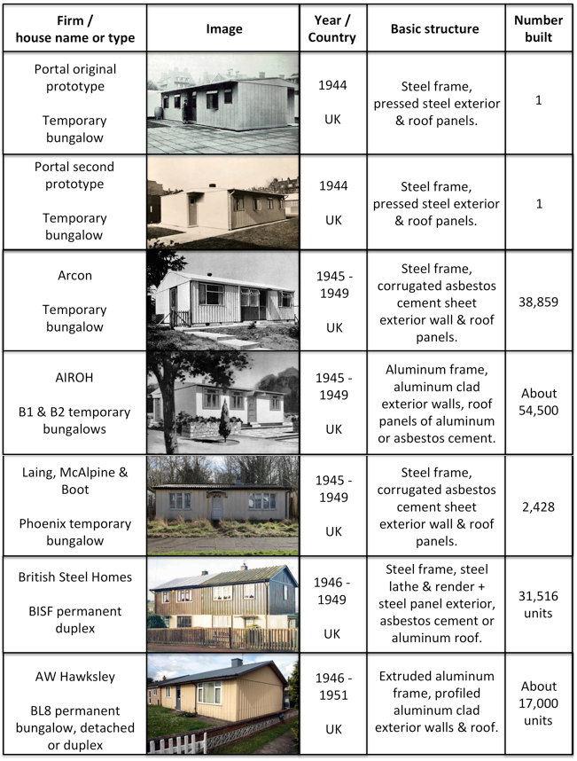
In 1944, the UK Ministry of Works held a public display at the Tate Gallery in London of five types of prefabricated temporary houses.
The original Portal all-steel prototype bungalow
The AIROH (Aircraft Industries Research Organization on Housing) aluminum bungalow, made from surplus aircraft material.
The Arcon steel-framed bungalow with asbestos concrete panels. This deign was adapted from the all-steel Portal prototype.
Two timber-framed prefab designs, the Tarran and the Uni-Seco
This popular display was held again in 1945 in London.
Supply chain issues slowed the start of the EFM program. The all-steel Portal was abandoned in August 1945 due to a steel shortage. In mid-1946, a wood shortage affected other prefab manufacturers. Both the AIROH and Arcon prefab houses were faced with unexpected manufacturing and construction cost increases, making these temporary bungalows more expensive to build than conventionally constructed wood and brick houses.
Under a Lend-Lease Program announced in February 1945, the US agreed to supply the UK with US-built, wood frame prefabricated bungalows known as the UK 100. The initial offer was for 30,000 units, which subsequently was reduced to 8,000. This Lend-Lease agreement came to an end in August 1945 as the UK started to ramp up its own production of prefabricated houses. The first US-built UK 100 prefabs arrived in late May/early June 1945.
The UK’s post-war housing reconstruction program was quite successful, delivering about 1.2 million new houses between 1945 and 1951. During this reconstruction period, 156,623 temporary prefabricated homes of all types were delivered under the EFM program, which ended in 1949, providing housing for about a half million people. Over 92,800 of these were temporary aluminum and steel bungalows. The AIROH aluminum bungalow was the most popular EFM model, followed by the Arcon steel frame bungalow and then the wood frame Uni-Seco. In addition, more than 48,000 permanent aluminum and steel prefabricated houses were built by AW Hawksley and BISF during that period.
In comparison to the very small number of post-war aluminum and steel prefabricated houses built in the US, the post-war production of aluminum and steel prefabs in the UK was very successful.
UK post-WW II prefabricated aluminum and steel houses
In a 25 June 2018 article in the Manchester Evening News, author Chris Osuh reported that, “It’s thought that between 6 or 7,000 of the post-war prefabs remain in the UK…..” The Prefab Museum maintains a consolidated interactive map of known post-WW II prefab house locations in the UK at the following link: https://www.prefabmuseum.uk/content/history/map
Screenshot of the Prefab Museum’s interactive map (not including the prefabs in the Shetlands, which are off the top of this screenshot).
In the UK, Grade II status means that a structure is nationally important and of special interest. Only a few post-war temporary prefabs have been granted the status as Grade II listed properties:
In an estate of Phoenix steel frame bungalows built in 1945 on Wake Green Road, Moseley, Birmingham, 16 of 17 homes were granted Grade II status in 1998.
Six Uni-Seco wood frame bungalows built in 1945 – 46 in the Excalibur Estate, Lewisham, London were granted Grade II status in 2009. At that time, Excalibur Estates had the largest number of WW II prefabs in the UK: 187 total, of several types.
Several post-war temporary prefabs are preserved at museums in the UK and are available to visit.
St. Fagans National Museum of History in Cardiff, South Wales: An AIROH B2 originally built near Cardiff in 1947 was dismantled and moved to its current museum site in 1998 and opened to the public in 2001. You can see this AIROH B2 here: https://museum.wales/stfagans/buildings/prefab/
Chiltern Open Air Museum (COAM) in Chalfont St. Giles, Buckinghamshire: Their collection includes a wood frame Universal House Mark 3 prefab manufactured by Universal Housing Company of Rickmansworth, Hertfordshire. This prefab was built in 1947 in the Finch Lane Estate in Amersham. You can see the “Amersham Prefab” here: https://www.coam.org.uk/museum-buckinghamshire/historic-buildings/amersham-prefab/
I think the Prefab Museum is best source for information on UK post-WW II prefabs. When it was created in March 2014 by Elisabeth Blanchet (author of several books and articles on UK prefabs) and Jane Hearn, the Prefab Museum had its home in a vacant prefab on the Excalibur Estate in south London. After a fire in October 2014, the physical museum closed but has continued its mission to collect and record memories, photographs and memorabilia, which are presented online via the Prefab Museum’s website at the following link: https://www.prefabmuseum.uk
You’ll find more information in my articles on specific UK post-WW II prefabricated aluminum and steel houses at the following links:
4. Post-WW II prefab aluminum and steel houses in France
At the end of WW II, France, like the UK, had a severe housing shortage due to the great number of houses and apartments damaged or destroyed during the war years, the lack of new construction during that period, and material shortages to support new construction after the war.
To help relieve some of the housing shortage in 1945, the French Reconstruction and Urbanism Minister, Jean Monnet, purchased the 8,000 UK 100 prefabricated houses that the UK had acquired from the US under a Lend-Lease agreement. These were erected in the Hauts de France (near Belgium), Normandy and Brittany, where many are still in use today.
The Ministry of Reconstruction and Town Planning established requirements for temporary housing for people displaced by the war. Among the initial solutions sought were prefabricated dwellings measuring 6 x 6 meters (19.6 x 19.6 feet); later enlarged to 6 × 9 meters (19.6 x 29.5 feet).
About 154,000 temporary houses (the French called then “baraques”), in many different designs, were erected in France in the post-war years, primarily in the north-west of France from Dunkirk to Saint-Nazaire. Many were imported from Sweden, Finland, Switzerland, Austria and Canada.
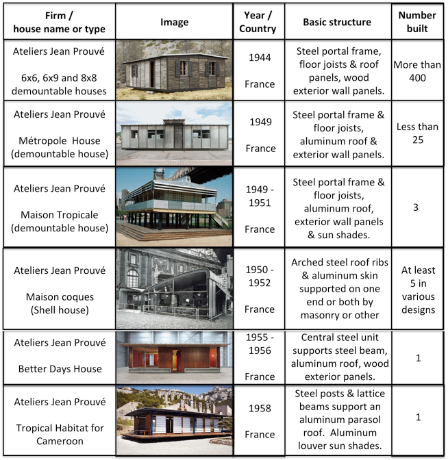
The primary proponent of French domestic prefabricated aluminum and steel house manufacturing was Jean Prouvé, who offered a novel solution for a “demountable house,” which could be easily erected and later “demounted” and moved elsewhere if needed. A steel gantry-like “portal frame” was the load-bearing structure of the house, with the roof usually made of aluminum, and the exterior panels made of wood, aluminum or composite material. Many of these were manufactured in the size ranges requested by Ministry of Reconstruction. During a visit to Prouvé’s Maxéville workshop in 1949, Eugène Claudius-Petit, then the Minister of Reconstruction and Urbanism, expressed his determination to encourage the industrial production of “newly conceived (prefabricated) economical housing.”
French post-WW II prefabricated aluminum and steel houses
Today, many of Prouvé’s demountable aluminum and steel houses are preserved by architecture and art collectors Patrick Seguin (Galerie Patrick Seguin) and Éric Touchaleaume (Galerie 54 and la Friche l’Escalette). Ten of Prouvé’s Standard Houses and four of his Maison coques-style houses built between 1949 – 1952 are residences in the small development known as Cité “Sans souci,” in the Paris suburbs of Muedon.
Prouvé’s 1954 personal residence and his relocated 1946 workshop are open to visitors from the first weekend in June to the last weekend in September in Nancy, France. The Musée des Beaux-Arts de Nancy has one of the largest public collections of objects made by Prouvé.
Author Elisabeth Blanchet reports that the museum “Mémoire de Soye has managed to rebuild three different ‘baraques’: a UK 100, a French one and a Canadian one. They are refurbished with furniture from the war and immediate post-war era. Mémoire de Soye is the only museum in France where you can visit post-war prefabs.” The museum is located in Lorient, Brittany. Their website (in French) is here: http://www.soye.org
The three wood frame ‘baraques’ at Mémoire de Soye. Source: Elisabeth Blanchet via the Prefab Museum (UK)
In the U.S., the post-war mass production of prefabricated aluminum and steel houses never materialized. Lustron was the largest manufacturer with 2,498 houses. In the UK, over 92,800 prefabricated aluminum and steel temporary bungalows were built as part of the post-war building boom that delivered a total of 156,623 prefabricated temporary houses of all types between 1945 and 1949, when the program ended. In France, hundreds of prefabricated aluminum and steel houses were built after WW II, with many being used initially as temporary housing for people displaced by the war. Opportunities for mass production of such houses did not develop in France.
The lack of success in the U.S. arose from several factors, including:
High up-front cost to establish a mass-production line for prefabricated housing, even in a big, surplus wartime factory that was available to the house manufacturer on good financial terms.
Immature supply chain to support a house manufacturing factory (i.e., different suppliers are needed than for the former aircraft factory).
Ineffective sales, distribution and delivery infrastructure for the manufactured houses.
Diverse, unprepared local building codes and zoning ordnances stood in the way of siting and erecting standard design, non-conventional prefab homes.
Opposition from construction unions and workers that did not want to lose work to factory-produced homes.
Only one manufacturer, Lustron, produced prefab houses in significant numbers and potentially benefitted from the economics of mass production. The other manufacturers produced in such small quantities that they could not make the transition from artisanal production to mass production.
Manufacturing cost increases reduced or eliminated the initial price advantage predicted for the prefabricated aluminum and steel houses, even for Lustron. They could not compete on price with comparable conventionally constructed houses.
In Lustron’s case, charges of corporate corruption led the Reconstruction Finance Corporation to foreclose on Lustron’s loans, forcing the firm into an early bankruptcy.
From these post-WW II lessons learned, and with the renewed interest in “tiny homes”, it seems that there should be a business case for a modern, scalable, smart factory for the low-cost mass-production of durable prefabricated houses manufactured from aluminum, steel, and/or other materials. These prefabricated houses could be modestly-sized, modern, attractive, energy efficient (LEED-certified), and customizable to a degree while respecting a basic standard design. These houses should be designed for mass production and siting on small lots in urban and suburban areas. I believe that there is a large market in the U.S. for this type of low-price housing, particularly as a means to address the chronic affordable housing shortages in many urban and suburban areas. However, there still are great obstacles to be overcome, especially where construction industry labor unions are likely to stand in the way and, in California, where nobody will want a modest prefabricated house sited next to their McMansion.
You can download a pdf copy of this post, not including the individual articles, here:
Blaine Stubblefield, “Aircraft Industry Will Make Aluminum Houses for Veterans,” Aviation News, Vol. 6, No. 10, 2 September 1946 (available in the Aviation Week & Space Technology magazine online archive)
“Battle for Aluminum Discounted by NHA,” Aviation News magazine, p. 22, 14 October 1946 (available in the Aviation Week & Space Technology magazine online archive)
Nicole C. Rudolph, “At Home in Postwar France – Modern Mass Housing and the Right to Comfort,” Berghahn Monographs in French Studies (Book 14), Berghahn Books, March 2015, ISBN-13: 978-1782385875. The introduction to this book is available online at the following link: https://berghahnbooks.com/downloads/intros/RudolphAt_intro.pdf
Kenny Cupers, “The Social Project: Housing Postwar France,” University Of Minnesota Press, May 2014, ISBN-13: 978-0816689651
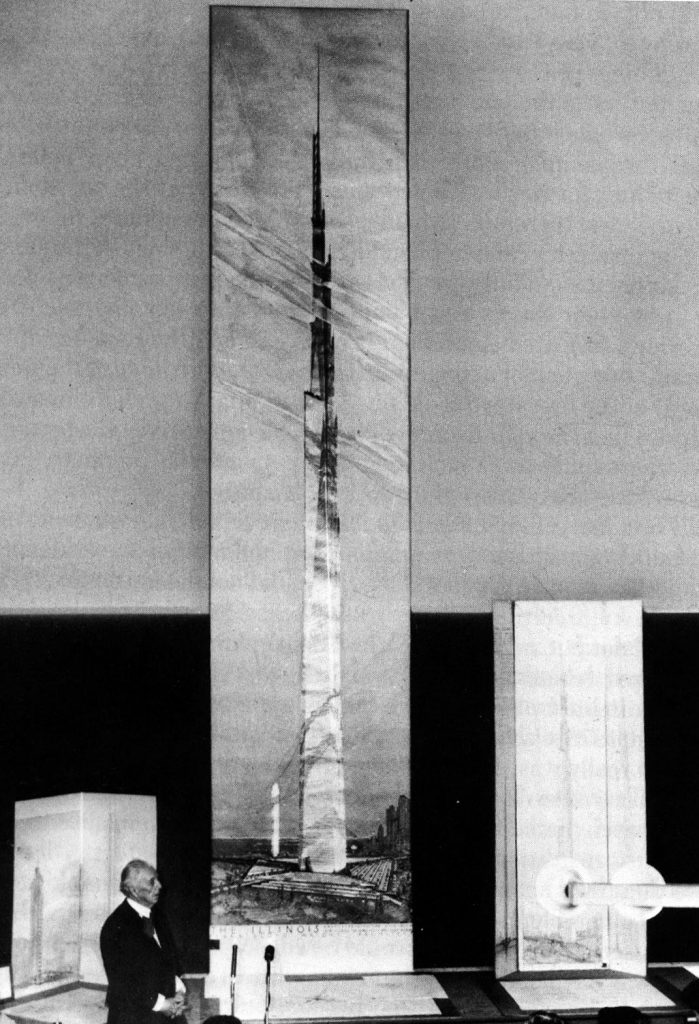
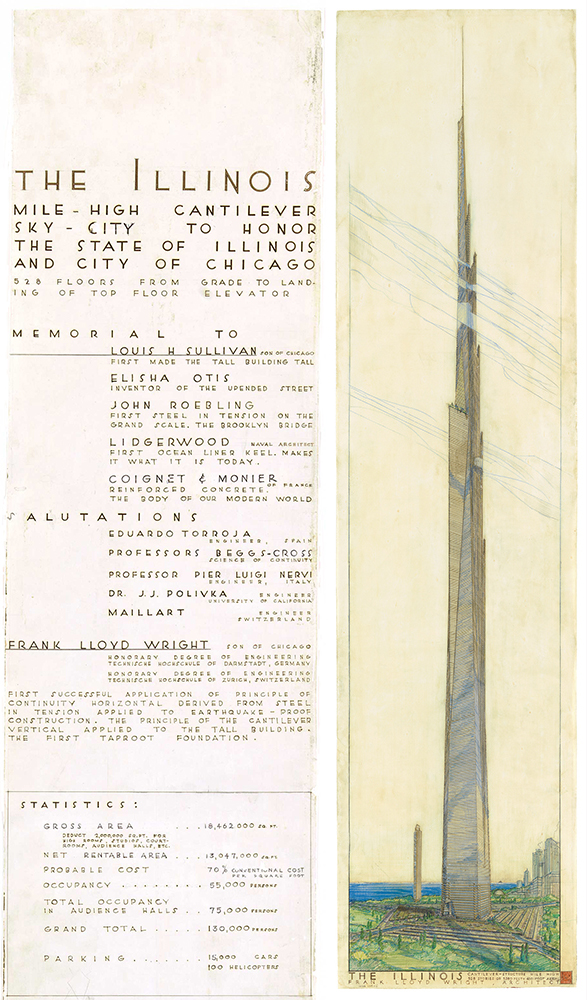
On 16 October 1956, architect Frank Lloyd Wright, then 89 years old, unveiled his design for the tallest skyscraper in the world, a remarkable mile-high tripod spire named “The Illinois,” proposed for a site in Chicago.
Frank Lloyd Wright. Source: Al Ravenna via Wikipedia
Also known as the Illinois Mile-High Tower, Wright’s skyscraper would stand 528 floors and 5,280 feet (1,609 meters) tall plus antenna; more than four times the height of the Empire State Building in New York City, then the tallest skyscraper in the world at 102 floors and 1,250 feet (380 meters) tall plus antenna. At the unveiling of The Illinoisat the Sherman House Hotel in Chicago, Wright presented an illustration measuring more than 25 feet (7.6 meters) tall, with the skyscraper drawn at the scale of 1/16 inch to the foot.
Frank Lloyd Wright presents The Illinois at the Sherman House Hotel in Chicago on 26 October 1956. Source: IBM.com/blog
Basic parameters for The Illinois are listed below:
Floors, above grade level: 528
Height:
Architectural: 5,280 ft (1,609.4 m)
To tip of antenna: 5,706 ft (1739.2 m)
Number of elevators: 76
Gross floor area (GFA): 18,460,106 ft² (1,715,000 m²)
Number of occupants: 100,000
Number of parking spaces: 15,000
Structural material:
Core: Reinforced concrete
Cantilevered floors: Steel
Tensioned tripod: Steel
The Illinois was intended as a mixed-use structure designed to spread urbanization upwards rather than outwards. The Illinois offered nearly three times the gross floor area (GFA) of the Pentagon, and more than seven times the GFA of the Empire State Building for use as office, hotel, residential and parking space. Wright said the building could consolidate all government offices then scattered around Chicago.
The single super-tall skyscraper was intended to free up the ground plane by eliminating the need for other large skyscrapers in its vicinity. This was consistent with Wright’s distributed urban planning concept known as Broadacre City, which he introduced in the mid-1930s and continued to advocate until his death in 1959.
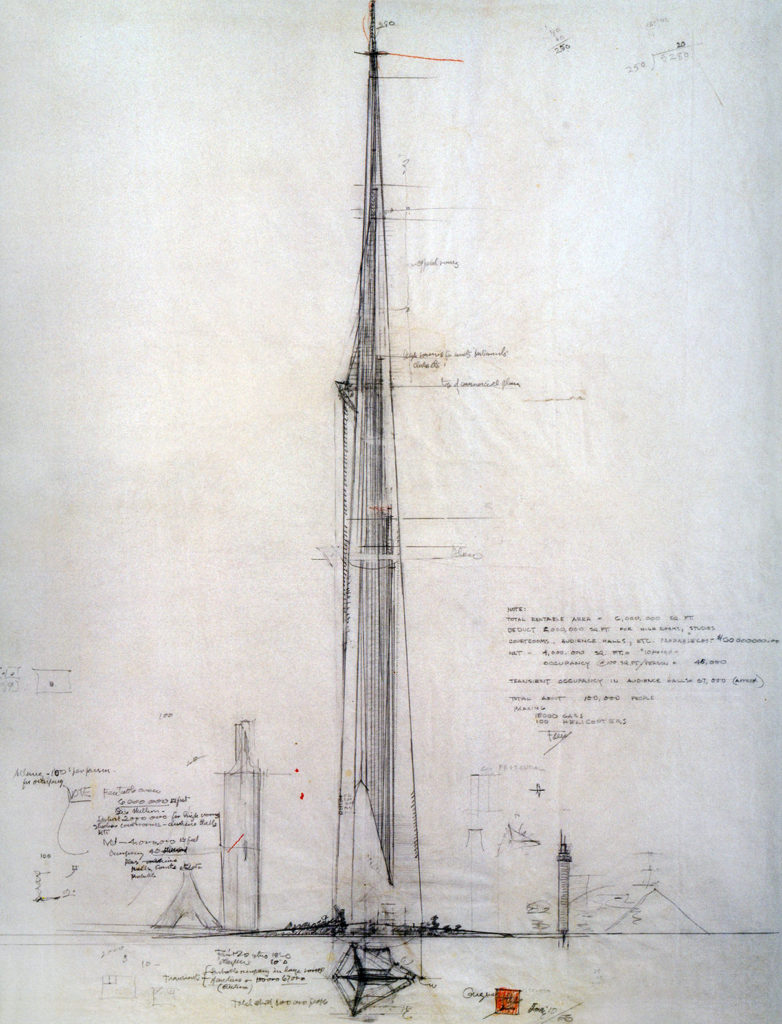
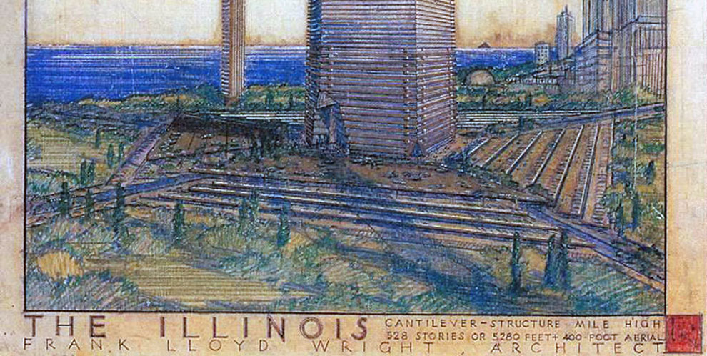
Sketch for Frank Lloyd Wright’s proposed mile high skyscraper, The Illinois. Source: Wright Mile Gallery, MCM Daily
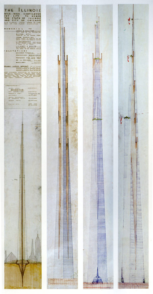
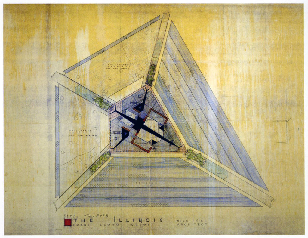
Frank Lloyd Wright illustrations of The Illinois. L to R: Cross-section; Back exterior view; Front exterior view; Side exterior view. Source: Wright Mile Gallery, MCM DailyClose-up view of the five-story base of The Illinois. Source: Frank Lloyd Wright FoundationIllustration of the footprint of The Illinois base and tower. Source: Source: Wright Mile Gallery, MCM DailyFrank Lloyd Wright illustration of The Illinois, showing the five-story base structure and the transition of the central reinforced concrete core into the “taproot” foundation structure. In the background are scale silhouettes of famous tall structures: Eiffel Tower, the Great Pyramid, and Washington Monument. Source: Wright Mile Gallery, MCM Daily
2. Tenuity, continuity and evolution of Wright’s concept for an organic high-rise building
Two aspects of Wright’s concept of organic architecture are the structural principles he termed “tenuity” and “continuity,” both of which he applied in the context of cantilevered and cable-supported structures, such as slender buildings and bridges. Author Richard Cleary reported that Wright first used the term tenuity in his 1932 book Autobiography, and offered his most succinct explanation in his 1957 book Testament.
“The cantilever is essentially steel at its most economical level of use. The principle of the cantilever in architecture develops tenuity as a wholly new human expression, a means, too, of placing all loads over central supports, thereby balancing extended load against opposite extended load.”
“This brought into architecture for the first time another principle in construction – I call it continuity – a property which may be seen as a new, elastic, cohesive, stability. The creative architect finds here a marvelous new inspiration in design. A new freedom involving far wider spacing of more slender supports.”
“Thus architecture arrived at construction from within outward rather than from outside inward; much heightening and lightening of proportions throughout all building is now economical and natural, space extended and utilized in a more liberal planning than the ancients could ever have dreamed of. This is now the prime characteristic of the new architecture called organic.”
“Construction lightened by means of cantilevered steel in tension makes continuity a most valuable characteristic of architectural enlightenment.”
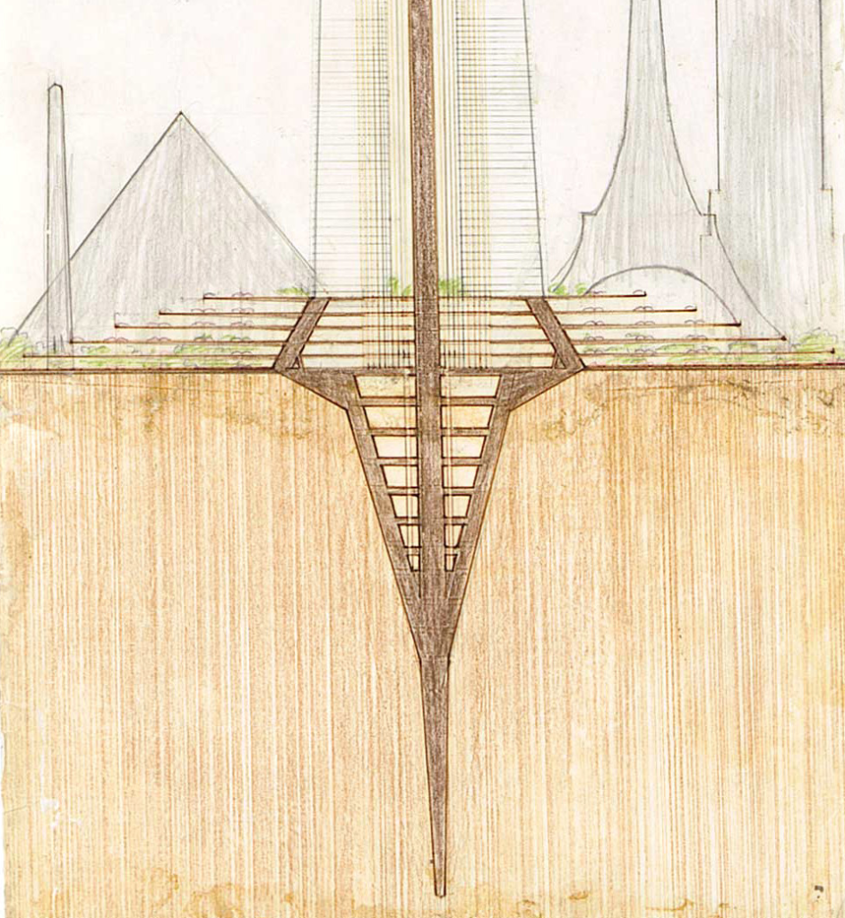
The structural principles of tenuity and continuity are manifest in Wright’s high-rise building designs that are characterized by a deep “taproot” foundation that supports a central load bearing core structure from which the individual floors are cantilevered. A cross-section of the resulting building structure has the appearance of a tree deeply rooted in the Earth with many horizontal branches.
Before looking further at the Mile-High Skyscraper, we’ll take a look at three of its high-rise predecessors and one later design, all of which shared Wright’s characteristic organic architectural features derived from the application of tenuity and continuity: taproot foundation, load-bearing core structure and cantilevered floors:
St. Mark’s Tower project
SC Johnson Research Tower
Price Tower
The Golden Beacon
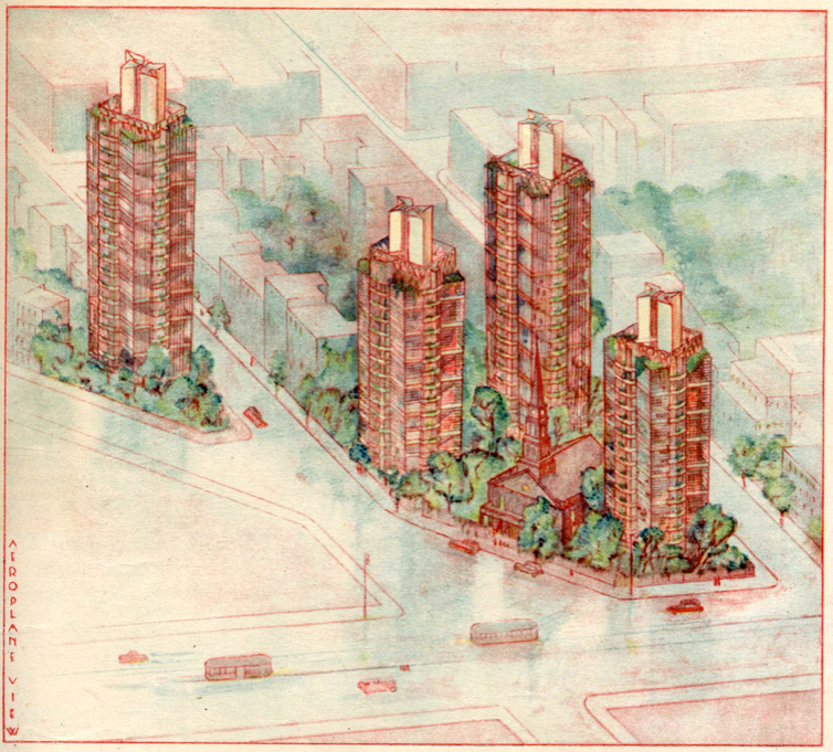
St. Mark’s Tower project (St. Mark’s-in-the-Bouwerie, 1927 – 1931, not built)
Wright first proposed application of the taproot foundation, load-bearing concrete and steel core structure and cantilevered floors was in 1927 for the 15-floor St. Mark’s Tower project in New York City.
The planned St. Mark’s Tower project in the Bowery, New York City. Source: Architectural Record, 1930, via The New YorkerSt. Mark’s Tower exterior view (L) and cross-section (R) showing the central core and cantilevered floors. The deep taproot part of the foundation is not shown. Sources: (L) Architectural Record, 1930, viaThe New Yorker; (R) adapted from Frank Lloyd Wright Foundation drawing
The New York Metropolitan Museum of Modern Art (MoMA) provides this description of the St. Mark’s Tower project.
“The design of these apartment towers for St. Mark’s-in-the-Bouwerie in New York City stemmed from Wright’s vision for Usonia, a new American culture based on the synthesis of architecture and landscape. The organic “tap-root” structural system resembles a tree, with a central concrete and steel load-bearing core rooted in the earth, from which floor plates are cantilevered like branches.”
“This system frees the building of load-bearing interior partitions and supports a modulated glass curtain wall for increased natural illumination. Floor plates are rotated axially to generate variation from one level to the next and to distinguish between living and sleeping spaces in the duplex apartments.”
While the St. Mark’s Tower project was not built, this basic high-rise building design reappeared from the mid-1930s to the mid-1960s as a “city dweller’s unit” in Wright’s Broadacre City plan and was the basis for the Price Tower built in the 1950s.
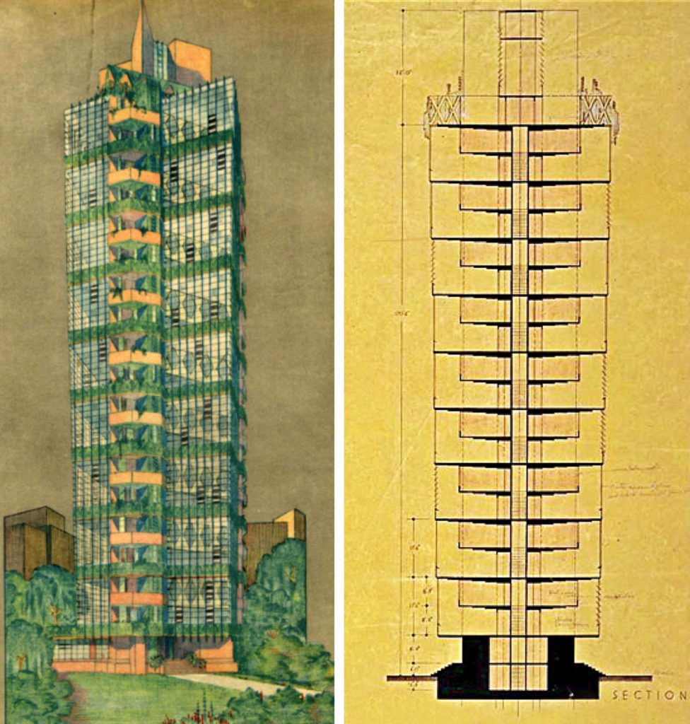
SC Johnson Research Tower, Racine, WI (1943 – 1950)
The 15-floor, 153 foot (46.6 m) tall SC Johnson Research Laboratory Tower, built between 1943 and 1950 in Racine, WI, was the first high-rise building to actually apply Wright’s organic design with a taproot foundation, load-bearing concrete and steel core structure and cantilevered floors. On their website, SC Johnson describes the structural design of this building as follows:
“One of Frank Lloyd Wright’s famous buildings, the tower rises more than 150 feet into the air and is 40 feet square. Yet at ground level, it’s supported by a base only 13 feet across at its narrowest point. As a result, the tower almost seems to hang in the air – a testament to creativity and an inspiration for the innovative products that would be developed inside.”
“Alternating square floors and round mezzanine levels make up the interior, and are supported by the “taproot” core, which also contains the building’s elevator, stairway and restrooms. The core extends 54 feet into the ground, providing stability like the roots of a tall tree.”
Because of the change in fire safety codes, and the impracticality of retrofitting the building to meet current code requirements, SC Johnson has not used the Research Tower since 1982. However, they restored the building in 2013 and now the public can visit as part of the SC Johnson Campus Tour.
You can make reservations at the following link for the Campus Tour and a separate tour of the nearby Herbert F. Johnson Prairie-style home, Wingspread, also designed by Frank Lloyd Wright: https://reservations.scjohnson.com/Info.aspx?EventID=8
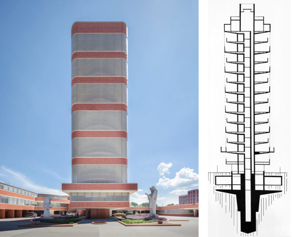
Price Tower, Bartlesville, OK (1952 – 1956)
The 19-floor, 221 foot (67.4 m) tall Price Tower, completed in 1956 in Bartlesville, OK, is an evolution of Wright’s 1927 design for the St. Mark’s Tower project. Wright nicknamed the Price Tower, “the tree that escaped the crowded forest,” referring to the building’s cantilever construction and the origin of its design in a project for New York City. Price Tower also has been called the “Prairie Skyscraper.”
H.C. Price commissioned Frank Lloyd Wright to design Price Tower, which served as his corporate headquarters until 1981 when it was sold to Phillips Petroleum. Philips deemed the exterior exit staircase a safety risk and only used the building for storage until 2000, when the building was donated to the Price Tower Arts Center. Since then, Price Tower has been returned to its multi-use origins and public tours are offered, including a visit to the restored 19th floor executive office of H.C. Price and the H.C. Price Company corporate apartment with the original Wright interiors. You can arrange your tour here: https://www.pricetower.org/tour/
You also can stay at the Inn at Price Tower, which has seven guest rooms. You’ll find details here: https://www.pricetower.org/stay/
The Golden Beacon, Chicago, IL (1959, not built)
The Golden Beacon was a concept for a 50-floor mixed-use office and residential apartment building in Chicago, IL.
The Golden Beacon exterior view (L), cross-section showing taproot foundation, central core and cantilever floors. (R). Sources: (L) https://stoutbooks.com/, (R) Richard Cleary, “Lessons in Tenuity….”
As shown in the cross-section diagram, the building design followed Wright’s practice with a deep taproot foundation, a central load-bearing core and cantilevered floors. This design is very similar to the foundation structure proposed for the earlier Mile-High Skyscraper.
The Golden Beacon exterior view. Source: Frank Lloyd Wright Foundation via https://treedowntown.com/
3. Extrapolating to the Mile-High Skyscraper
By 1956, Wright’s characteristic organic architectural features for high-rise buildings, derived from the application of tenuity and continuity, had only appeared in two completed high-rise buildings, the 15-floor SC Johnson Laboratory Tower and the 19-floor Price Tower. These two important buildings demonstrated the practicality of the taproot foundation, load-bearing concrete and steel core structure and cantilevered floors for tall, slender buildings. With the unveiling of The Illinois, Wright made a remarkable extrapolation of these architectural principles in his conceptual design of this breathtaking 528 floor, 5,280 feet (1,609 meters) tall skyscraper.
Blaire Kamin, writing for the Chicago Tribune in 2017, reported: “The Mile-High didn’t simply aim to be tall. It was the ultimate expression of Wright’s “taproot” structural system, which sank a central concrete mast deep into the ground and cantilevered floors from the mast. In contrast to a typical skyscraper, in which same-size floors are piled atop one another like so many pancakes, the taproot system lets floors vary in size, opening a high-rise’s interior and letting space flow between floors.”
In addition to the central core to support the building’s dead loads, The Illinois also incorporated an external tensioned steel tripod structure to resist external wind loads and other flexing loads (i.e., earthquakes), distributing those loads through the integral steel structure of the tripod, and resisting oscillations. In his book, “Testament,” Wright stated:
“Finally – throughout this lightweight tensilized structure, because of the integral character of all members, loads are at equilibrium at all points, doing away with oscillations. There would be no sway at the peak of The Illinois.”
Tuned mass dampers (TMD) for reducing the amplitude of mechanical vibrations in tall buildings had not been invented when Wright unveiled his design for The Illinois in 1956. The first use of a TMD in a skyscraper did not occur until the mid-1970s, first as a retrofit to the troubled, 790 foot (241 m) tall, John Hancock building completed in 1976 in Boston, and then as original equipment in the 915 foot (279 m) tall Citicorp Tower completed in 1977 in New York City. While tenuity and continuity may have given The Illinois unparalleled structural stability, I wouldn’t be surprised if TMD technology would have been needed for the comfort of the occupants on the upper floors, three-quarters of a mile above their counterparts in the next tallest building in the world.
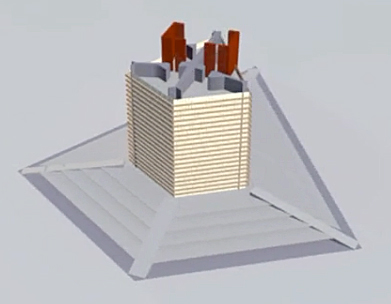
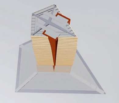
To handle its 100,000 occupants, The Illinois had 76 elevators that were divided into five groups, each serving a 100-floor segment of the building, with a single elevator serving only the top floors. Each elevator was a five-story unit that moved on rails and served five floors simultaneously. With the tapering, pyramidal shape of the skyscraper, the vertical elevator shaft structures eventually extended beyond the sloping exterior walls, forming protruding parapets on the sides of the building. In his 1957 book, “A Testament,” Wright said the elevators were designed to enable building evacuation within one hour, in combination with the escalators that serve the lowest five floors.
Wright alluded to the building (and the elevators) being “atomic powered,” but there were no provisions for a self-contained power plant as part of the building. The much smaller Empire State Building currently has a peak electrical demand of almost 10 megawatts (MW) in July and August after implementing energy conservation measures. Scaling on the basis of gross floor area, The Illinois could have had a peak electrical demand of about 70 MW. You’ll find more information on current Empire State Building energy usage here: https://www.esbnyc.com/sites/default/files/esb_overall_retrofit_fact_sheet_final.pdf
The 2012 short video by Charles Muench, “A Peaceful Day in BroadAcre City – One Mile High – Frank Lloyd Wright” (1:31 minutes), depicts The Illinois skyscraper in the spacious setting of Broadacre City and shows an animated construction sequence of the tower. Two screenshots from the video are reproduced below. You’ll find this video at the following link: https://www.dailymotion.com/video/xp86uo
Two views of the start of The Illinois construction sequence. Screenshots from Charles Muench video, 2012.
You can see more architectural details in the 2009 video, “Mile High Final Movie – Frank Lloyd Wright” (3:42 minutes), produced for the Guggenheim Museum, New York. Two screenshots are reproduced below. You’ll find the video here: https://vimeo.com/4937909
The Illinois, showing architectural exterior details. Screenshot from Guggenheim video, 2009.
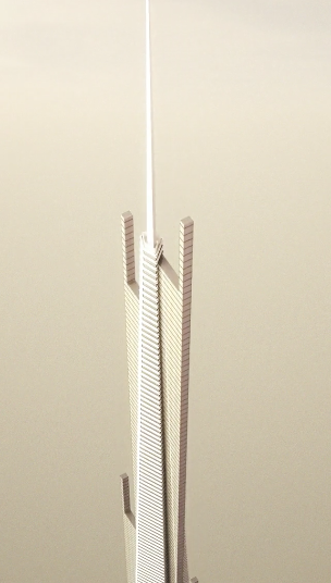
The top of The Illinois, showing details at the 528th floor, including the protruding parapets for the elevators, and the 420+ foot (128 m) antenna on top. Screenshot from Guggenheim video, 2009.
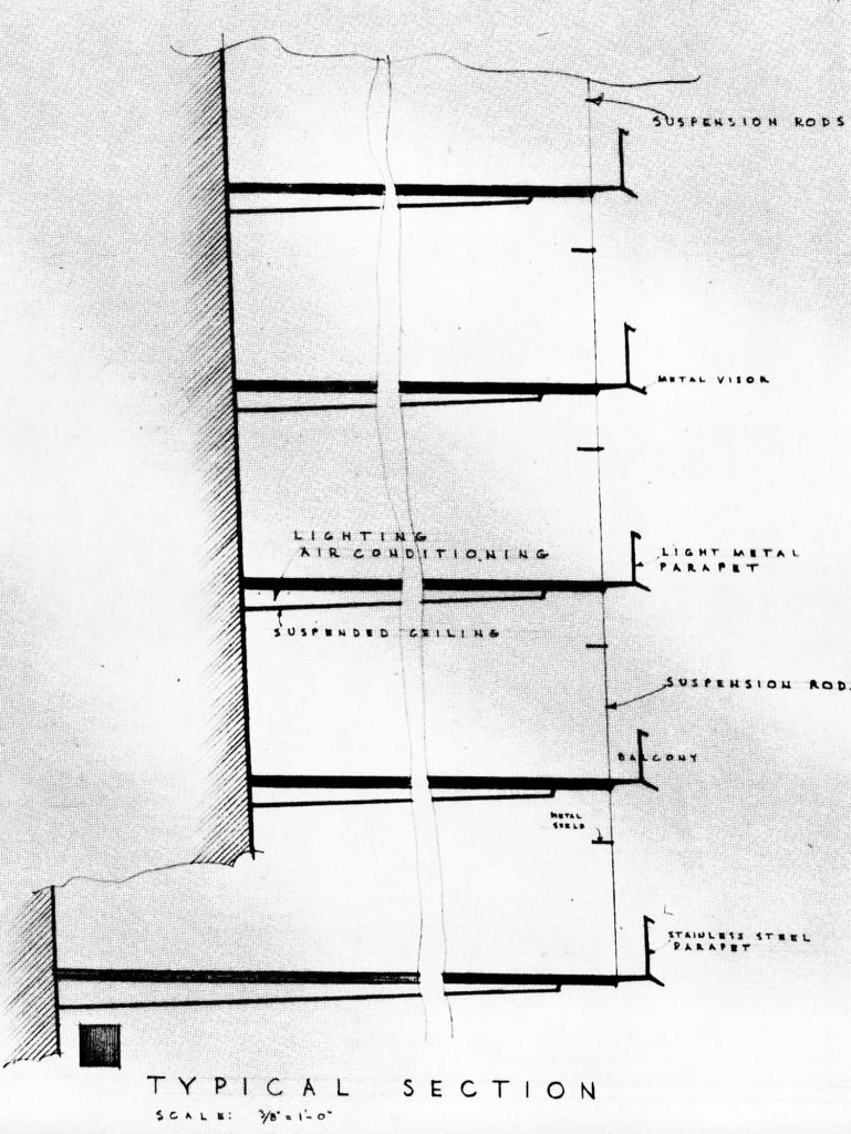
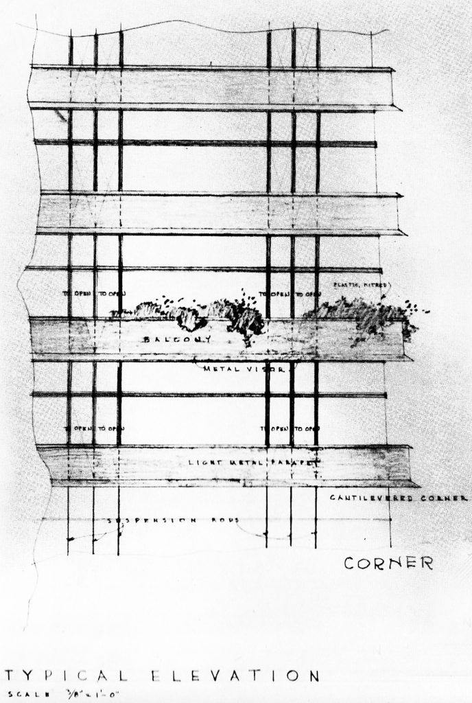
In his 1957 book, Testament, Wright provided the following two architectural drawings showing typical details of the cantilever construction of The Illinois.
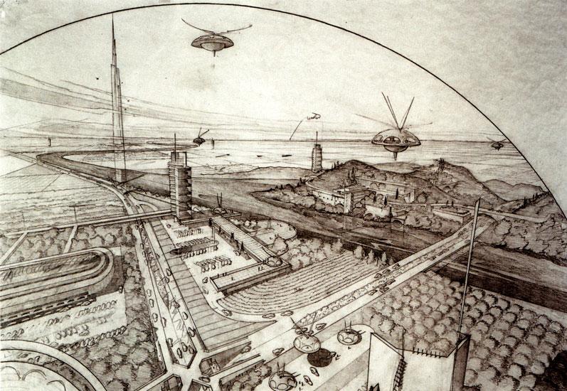
The Illinois was intended for construction in a spacious setting like Broadacre City, rather than in a congested big-city downtown immediately adjacent to other skyscrapers. Two views of The Illinois in these starkly different settings are shown below.
Model of The Illinois. Source: Milwaukee Sentinel Journal
The Illinois skyscraper as part of Frank Lloyd Wright’s mid-1950s landscape for his urban planning concept known as Broadacre City. Source: utopicus2013.blogspotArtist’s concept of The Illinois skyscraper punctuating a rather congested contemporary Chicago skyline, not quite as Frank Lloyd Wright envisioned. Source: Neoman Studios
4. Wright’s Mile-High Skyscraper on Exhibit at MoMA
Since Wright’s death in 1959, his archives have been in the care of the Frank Lloyd Wright Foundation (https://franklloydwright.org/frank-lloyd-wright/) and stored at Wright’s homes / architectural schools at Taliesin in Spring Green, WI and Taliesin West, near Scottsdale, AZ.
In September 2012, Mary Louise Schumacher, writing for the Milwaukee Sentinel Journal, reported that Columbia University and the Museum of Modern Art (MoMA) in Manhattan had jointly acquired the Frank Lloyd Wright archives, which consist of architectural drawings, large-scale models, historical photographs, manuscripts, letters and other documents. You’ll find her report here: http://archive.jsonline.com/newswatch/168457936.html
Columbia University’s Avery Architectural & Fine Arts Library (https://library.columbia.edu/libraries/avery/da.html) will be the keeper of all of Wright’s paper archives, as well as interview tapes, transcripts and films. MoMA (https://www.moma.org) will add Wright’s three-dimensional models to its permanent collection.
The Frank Lloyd Wright Foundation will retain all copyright and intellectual property responsibilities for the archives, and all three organizations hope to see the archives placed online at some point in the future.
On 12 June 2017, MoMA opened its exhibit, “Frank Lloyd Wright at 150: Unpacking the Archive,” which ran thru 1 October 2017. You can take an online tour of this exhibit, which included Wright’s plans for The Illinois, here: https://www.moma.org/calendar/exhibitions/1660
MoMA’s curator of the Wright collection, Barry Bergdoll, provided an introduction to the trove of recently acquired documentation on The Illinois in a short 2017 video (4:32 minutes) at the following link: https://www.youtube.com/watch?v=VhUDu0Q08UA
Plans and sketches for The Illinois mile-high skyscraper at the 2017 MoMA exhibit. Source: MoMA
Professor Allen Sayegh with Justin Chen & John Pugh, “Mile High Final Movie – Frank Lloyd Wright” (3:42), Harvard University Graduate School of Design for the Guggenheim Museum, New York, 2009: https://vimeo.com/4937909
My 11 December 2018 post, “Lots of Land Speed Record (LSR) Action in 2018,” provides background information on land speed record governance and a look at the fastest cars competing in the 2018 LSR season. 2018 highlights included:
The North American Eagle team, with driver Jessi Combs, continued to extend the performance of their jet-powered LSR car on a track in the Alvord Desert in Oregon.
The Bloodhound team in the UK was saved from insolvency, literally at the last moment, when the business and assets were bought by Yorkshire-based entrepreneur Ian Warhurst.
Salt conditions at the Bonneville salt flats in Utah were very good and many speed records were broken.
The North American Eagle LSR car crashed during a high-speed run in the Alvord Desert in August, killing driver Jessi Combs.
The salt conditions at the Bonneville salt flats were poor, resulting in rough driving conditions and generally lower speeds during Bonneville Speed Week (August) and the Utah Salt Flats Racing Association (USFRA) World of Speed (September). The Bonneville World Finals (October) were cancelled because of wet conditions.
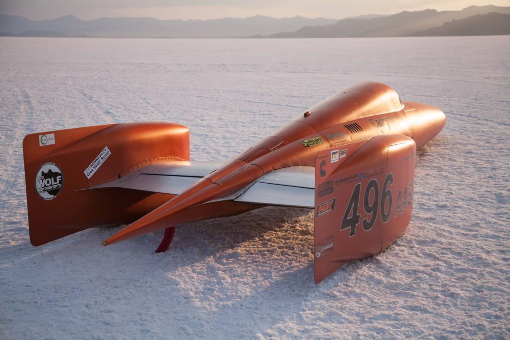
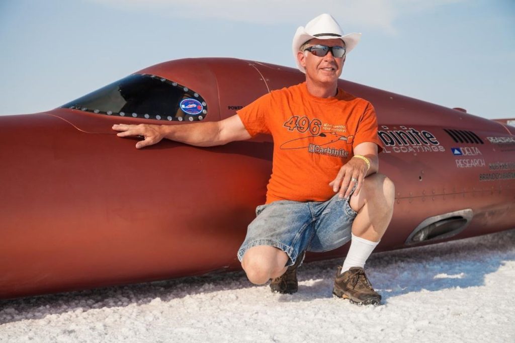
The Carbinite LSR car, the Carbiliner, crashed during a high-speed run at the World of Speed 2019 in September, severely injuring driver Rob Freyvogel.
The 29th Annual Speed Week at Lake Gairdner, Australia in March had only one run over 300 mph (483 kph) in hot, dry conditions.
Now with proper financing, the Bloodhound LSR team transitioned to the next phase of the project, arriving at the Hakskeen Pan track in South Africa in October and conducting high-speed testing, which concluded successfully in November.
Let’s take a look at the 2019 LSR season in more detail.
1. North American Eagle
In August 2019, the North American Eagle team, with driver Jessi Combs, returned to the Alvord Desert in Oregon to attempt to break the official Women’s Land Speed Record set by Kitty O’Neil in 1976 with a two-way average speed of 512.710 mph (825.127 kph) in the rocket-powered SMI Motivator at the same venue. The North American Eagle team website is here: https://www.landspeed.com
The North American Eagle land speed record car. Source: North American EagleDriver Jessi Combs. Source: North American Eagle
An investigation into the cause of the crash revealed that the front wheel assembly of the car collapsed, possibly due to collision damage from hitting something on the track at high speed.
North American Eagle Crew Chief Les Holm reported Jessi Combs’ second run was measured at a speed of 548.342 mph (882.471 kph), yielding a two-way average speed of 531.889 mph (855.992 kph). Hemmings news reported that the North American Eagle team has submitted Jessi Combs’s two-way average speed results to the Guinness Book of World Records to claim the title of fastest woman on the planet.
It is not yet known if Jessi Combs’ two-way average speed will qualify as an official FIA world land speed record.
The Petersen Automotive Museum in Los Angeles held an exhibition entitled “Jessi Combs: Life at Full Speed” to commemorate the life and accomplishments of this extraordinary person.
Source: Petersen Automotive Museum
The Jessi Combs Foundation was founded in 2019. The mission of the Foundation is to “educate, inspire and empower the next generation of female trailblazers and stereotype-breakers.” The Foundation’s website is here: https://www.thejessicombsfoundation.com/mission-statement/
In June 2020, the Guinness World Record was posthumously awarded to Jessi Combs, declaring: “The fastest land speed record (female) is 841.338 kph (522.783 mph), and was achieved by Jessi Combs (USA) in the Alvord Desert, Oregon, USA, on 27 August 2019. Jessi is the first person to break this record in more than 40 years.” This record is posted on the Guinness World Records website here: https://www.guinnessworldrecords.com/world-records/fastest-land-speed-record-(female)
2. Bonneville Speed Week 2019: 13 – 15 August 2019
Now let’s look at a few of the top challengers at Speed Week 2019.
Turbinator II
At the Bonneville World Finals in 2018, Team Vesco’s gas turbine powered Turbinator II, with Dave Spangler driving, made a one-way run through the measured mile of 493.996 mph (795.009 kph), with an exit speed of 503.332 mph (810.034 kph). Turbinator II became the world’s first wheel-driven vehicle to exceed 500 mph and 800 kph.
In 2019, Dave Spangler was unable to complete a single run with Turbinator II during Bonneville Speed Week 2019. Three runs on the 2-mile “short” course were attempted on 14 – 15 August, but none were completed, for a variety of issues. You can watch a short video about Team Vesco at Speed Week 2019 here:
After Speed Week 2019, Team Vesco reported, “In the interest of safety and to correct our course while navigating toward our goal to become the first wheel driven car to set an official National or World record over 500 MPH, we must discontinue racing for the remainder of 2019. To improve our team, we have already begun a search for a company with turbine control engineering capabilities to partner with us.” You’ll find more information on the Team Vesco website here: https://www.teamvesco.com
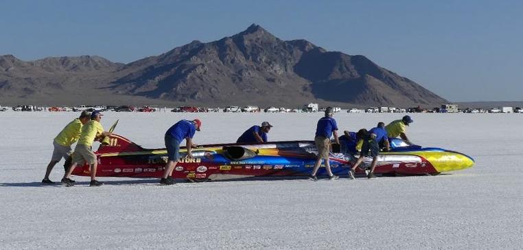
Speed Demon
George Poteet’s Speed Demon is a blown (supercharged or turbocharged) fuel (not gasoline) streamliner (BFS) that currently holds two-way land-speed records in five out of seven of Bonneville’s BFS classes: A, B, C, D and F. The two remaining classes are AA/BFS and E/BFS. The team’s goals for 2019 were to achieve records in these remaining classes and to raise its fastest two-way speed record to over 480 mph (772 kph). The teams current record, set in 2013, stands 437.183 mph (703.578). You can read more about these plans in the following Motor Tend article: https://www.hotrod.com/articles/pottet-speed-demon-aims-480-mph-bonneville/
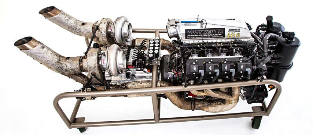
To compete in several different classes, Speed Demon is designed to accommodate several different displacement engines that have been configured to fit inside the car’s svelte fuselage. At Speed Week 2019, the team had four different Duttweiler engines to challenge BFS records in Classes A, AA, C and E.
Speed Demonwas the only car that made runs over 300 mph (483 kph) during Speed Week 2019. On the “long” course, which was shortened to two miles because of poor salt conditions, Speed Demon achieved the following speeds:
13 Aug 2019: 300.648 mph (483.846 kph) and 332.815 mph (535.614 kph) with the E “small block” engine
15 Aug 2019: 369.533 mph (594.706 kph) with the AA “big block” engine
None of these runs broke an existing class speed record. However, Speed Demon and George Poteet were honored with the Hot Rod Magazine trophy for fastest run during Speed Week 2019.
Tom Flattery’s Salt Shark, a Class B blown gas (gasoline) streamliner (B/BGS), made its first appearance at Bonneville Speed Week 2019. The Salt Shark is powered by a twin-turbo, 427 cubic inch, fuel injected LSX engine from Golen Engine Service in New Hampshire. Salt Shark reached a maximum speed of 290.568 mph (467.624 kph) on 15 August 2019, making it the second fastest car at Speed Week 2019 after Speed Demon. You’ll find more information on the Salt Shark Facebook page here: https://www.facebook.com/Bonneville-Salt-Shark-226594851348688/
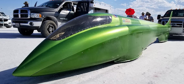
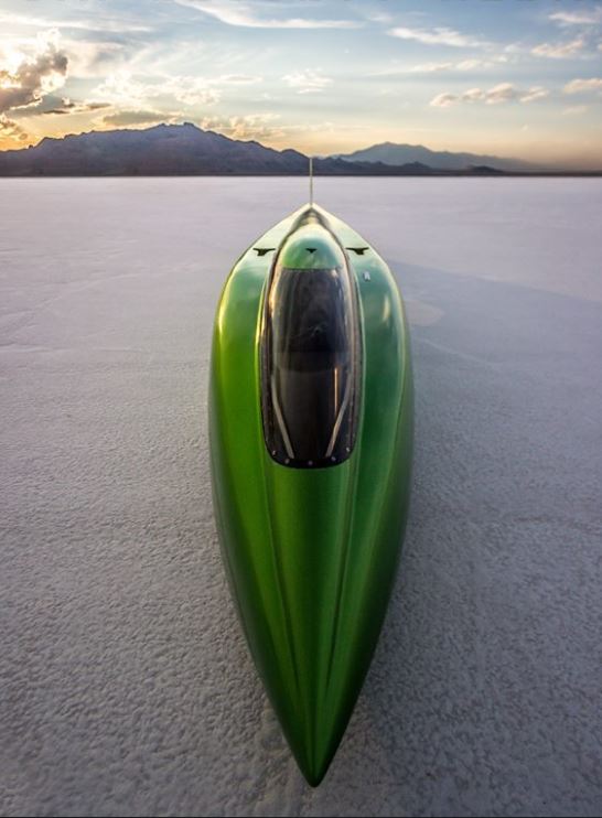
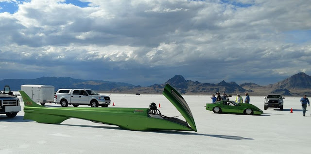
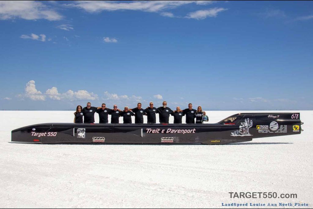
The Treit and Davenport Target 550 is a Class AA blown fuel streamliner (AA/BFS). At Bonneville Speed Week 2019, new driver Valerie Thompson took the car to a maximum speed of 270.762 mph (435.749 kph) on 15 August 2019. Rough salt conditions prevented a return run.
At the Utah Salt Flats Racing Association’s (USFRA) World of Speed event in October 2019, rough salt conditions persisted. The team reported, “On its first run, the car was bouncing up and down and bottoming almost from the start line. Valerie clocked at 291 mph (468 kph), but the car went airborne due to the rough course. Parts broke, damaging both engines. The drag chutes deployed properly and the car came to a safe stop. Thankfully no one was hurt.”
In January 2020, the Treit and Davenport team plans to ship Target 550 to Australia. With Valerie Thompson driving, the team will challenge the world speed record for its class in March 2020 during Speed Week at Australia’s Lake Gairdner.
3. Utah Salt Flats Racing Association (USFRA) World of Speed 2019: 16 – 16 September 2019
Like Bonneville Speed Week 2019, the USFRA World of Speed 2019 was affected by wet salt conditions. Results are posted on the USFRA website here: https://saltflats.com
Only three cars reached speeds greater than 300 mph (483 kph) on runs during World of Speed 2019. One of them, the Carbinite LSR car, the Carbiliner, was destroyed in a high-speed crash and the driver was seriously injured.
Let’s take a look at the three fastest LSR cars at this meet.
Carbinite LSR – Carbiliner
The Carbiliner is a Class AA blown fuel streamliner (AA/BFS). In 2018, it was one of five LSR vehicles to exceed 400 mph (644 kph) during Bonneville Speed Week, making runs of 406.750 mph (654.601 kph) and 413.542 mph (665.531 kph).
At World of Speed 2019, the Carbiliner, driven by Rob Freyvogel, crashed during a high-speed run on 15 September 2019. The car had been measured at an average speed of 392 mph (631 kph) and was still accelerating heading into the final mile of the long course when the crash occurred. While the rugged structure of the cockpit provided some protection, Rob Freyvogel was seriously injured.
The Strasburg family’s LSR car is a Class C blown fuel lakester (C/BFL). With almost perfect salt conditions at Bonneville in 2018, the Strasburg family set a new world land speed record for a lakester (an open-wheeled car) with an average speed of 373 mph (600 kph).
At World of Speed 2019, this lakester, driven by Anita Strasburg, exceeded 300 mph (483 kph) on several runs. On the best run, Anita Strasburg recorded 347.484 mph (559.221 kph) in the last (3rd) mile with an exit speed of 350.493 mph (564.064 kph).
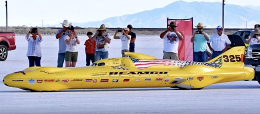
The Beamco is a Class D unblown gas streamliner (D/GS) owned by Team Vesco and driven by Bob Blakely.
The Beamco streamliner. Screenshot from Real Tuners video at USFRA 15 September 2019
In the following video, you can take a ride aboard the Beamco streamliner as Bob Blakely raised the D/GS 2-way average speed record to 312.664 mph (503.184 kph) during the World of Speed 2019 in rough course conditions.
Blakely also became a new 300 mph Club member.
4. Bonneville World Finals 2019
On 28 September 2019, Bill Lattin, SCTA President, reported: “Unfortunately Mother Nature is at again. We were able to drag a good course and now there is standing water on it. Due to the weather forecast coming we have decided to cancel World Finals.”
After being rescued from insolvency in December 2018 by Ian Warhurst, a new company called Grafton LSR Ltd. was formed in March 2019 to be the car’s legal owner. The team was renamed “Bloodhound LSR” and the team headquarters were moved to the UK Land Speed Record Center in Berkeley, Gloucestershire, UK. The Bloodhound LSR website is here: https://www.bloodhoundlsr.com
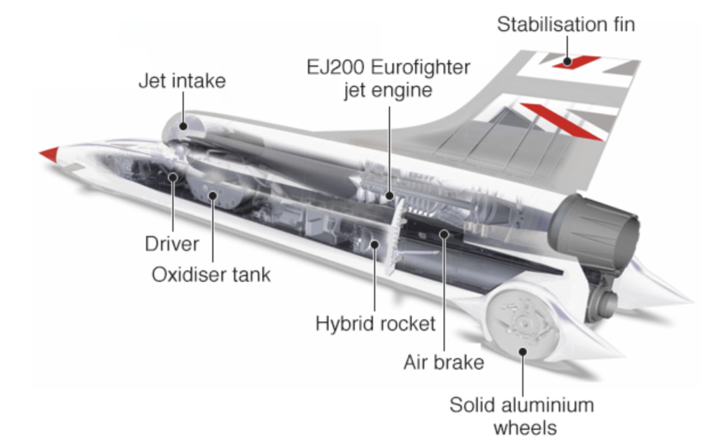
The configuration of the jet + rocket-propelled Bloodhound LSR is shown in the following diagram.
Source: Bloodhound LSR
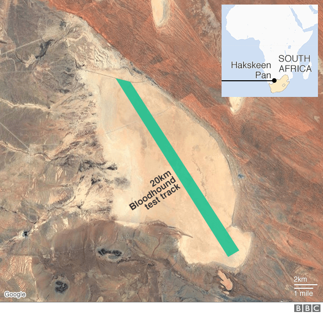
The team’s goal for 2019 was to conduct high-speed testing of the Bloodhound LSR at the intended land speed record venue, the Hakskeen Pan in South Africa. The Bloodhound LSR team states that high-speed testing is “needed to allow the team to test many aspects of the car and all operational procedures in advance of the world land speed record runs, currently planned for late 2020.”Hakskeen Pan is a very flat dry lake bed with the world’s largest “unworked” saltpan. A test track measuring 20 km (12.4 miles) long and 1,100 meters (0.68 mile) wide has been established on the saltpan for use by Bloodhound LSR. The layout of the test track on Hakskeen Pan is show in the following diagram. For more information on this test track, see my 8 September 2015 post, “Just How Flat is Hakskeen Pan?” here: https://lynceans.org/all-posts/just-how-flat-is-hakskeen-pan/
For the high-speed test phase, the Bloodhound LSR was propelled only by its EJ200 jet engine, which is rated at 90 kN (20,230 pounds) of thrust. This engine is based on Rolls-Royce gas turbine engine technology and is built by the EuroJet Turbo GmbH consortium. The Nammo hybrid rocket engine was not installed for the 2019 high-speed tests.
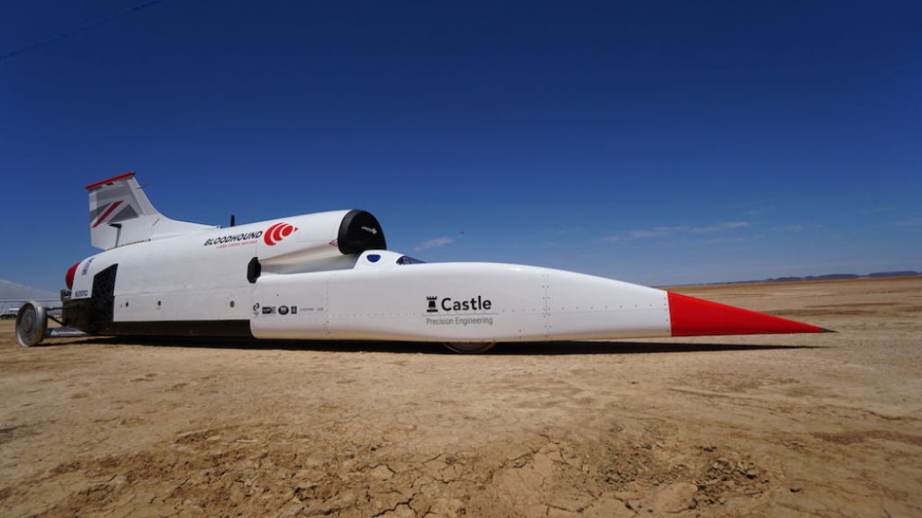
Completed Bloodhound LSR unveiled at Hakskeen Pan. Source, both photos: Bloodhound LSR
Test runs began on 27 October 2019, with Andy Green driving the Bloodhound LSR. Information on all of the test runs, and selected videos, are available on the Bloodhound LSR website, under the “News” tab. Here’s the direct link: https://www.bloodhoundlsr.com/category/bloodhound-lsr-news/
High-speed testing was completed on 17 November 2019 with a 628 mph (1,010 kph) run. The team was pleased to report, “Mission accomplished.” You can watch a short video of this final high-speed test run here.
BBC reported, “The car’s costs are currently being underwritten by wealthy Yorkshire businessman Ian Warhurst. He says the next phase of the project will have to be funded by others, most likely corporate sponsors….. ‘With the high-speed testing phase concluded, we will now move our focus to identifying new sponsors and the investment needed to bring Bloodhound back out to Hakskeen Pan in the next 12 to 18 months’ time.’”
Development continues on the hybrid rocket engine that will be added to the Bloodhound LSR for the next set of high-speed runs at Hakskeen Pan.
You’ll find my previous posts on the Bloodhound LSR team and car here:
6. 29th Annual Speed Week at Lake Gairdner, Australia
Speed Week at Lake Gairdner was held from 4 to 8 March 2019 in hot, dry weather with fair salt conditions. There was only one run over 300 mph (483 kph) at this meet. Jim Knapp’s #1584, the Knappsters Streamliner, which is a Class AA blown fuel streamliner (AA/BFS), made the top speed run of the meet at 309.438 mph (497.994 kph).
The record for the top speed run at the Annual Speed Week at Lake Gairdner was set in 2018 by Les Davenport driving the Treit and Davenport Target 550, another AA/BFS, at 345.125 mph (555.425 kph). Track conditions and weather were excellent in 2018. The Treit and Davenport team is planning to be back in 2020.
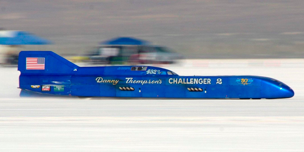
7. The world’s fastest piston-powered car, Challenger 2, is for sale
Challenger 2 is a Class AA unblown fuel streamliner (AA/FS). Danny Thompson’s record-setting 448.757 mph (722.204 kph) average runs in Challenger 2 during Bonneville Speed Week 2018 set a new official world land speed record for piston-powered cars.
In November 2019, Mecum Auctions announced that this famous streamliner will come up for auction at Mecum’s Kissimmee, Florida event in January 2020. No starting price has been announced. In case you’re interested, you’ll find Mecum’s listing for the Challenger 2 here: https://www.mecum.com/lots/FL0120-397299/1968-challenger-2-streamliner/
Challenger 2 at Bonneville Speed Week 2018. Source: Mecum Auctions
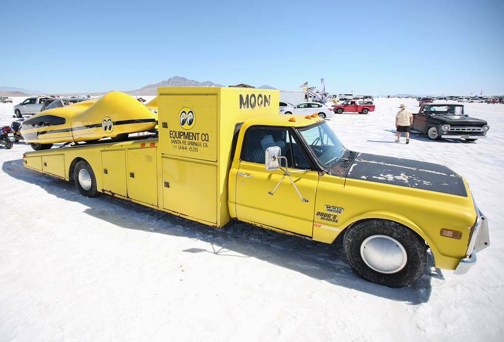
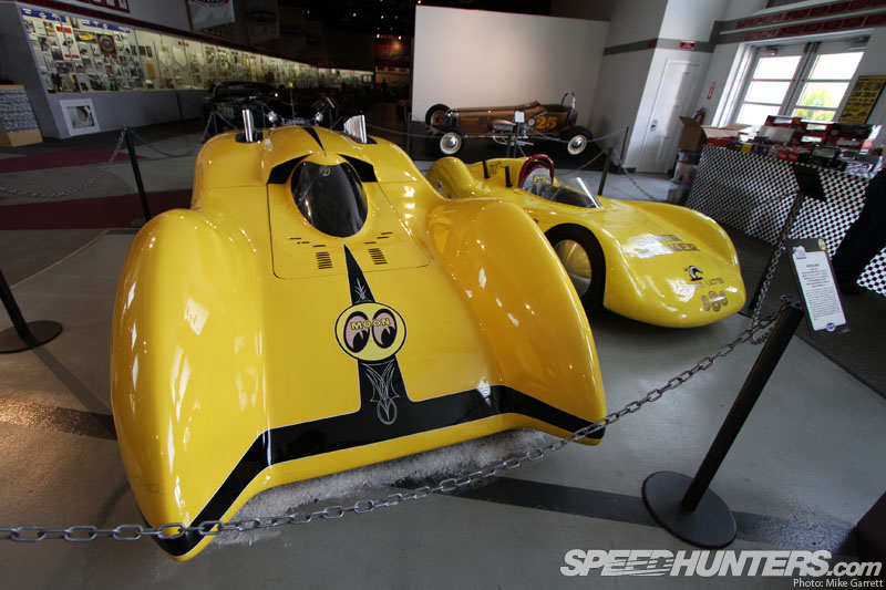
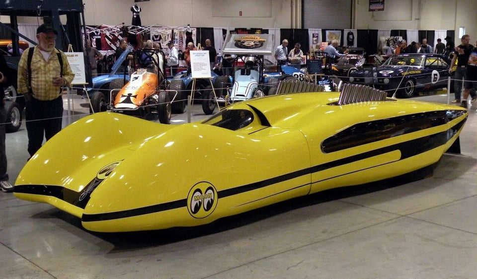
8. 1959 Mooneyes Moonliner on display at Speed Week 2019
At Bonneville Speed Week 2019, the beautiful 1959 Mooneyes Moonliner, built by Jocko Johnson for Dean Moon, was on display. This streamliner originally was powered by an Allison V-12 aircraft engine; later replaced by a fuel-injected, big-block Chevrolet engine. You can follow the Moonliner on Facebook here: https://www.facebook.com/Mooneyes/
The Moonliner was only run for exhibitions and car shows, and never competed at any speed trials. Nonetheless, the Moonliner is an exotic piece of rolling automotive art that could have been an exciting Class AA unblown gas streamliner (AA/GS).
In 1974, the Moonliner, powered by the big-block Chevrolet engine, driven by Gary Gabelich, and painted red and black (Budweiser colors) was at the Bonneville salt flats for a publicity run for Budweiser. The Moonliner is reported to have reached 285 mph (458 kph) during this event.
Mooneyes Moonliner at Bonneville. Source: 1974 Budweiser advertisement
You’ll find many historic photos of the Moonliner at Bonneville in 1974 on the Getty Images website at the following link. Be sure to check out the photos of the unusual exhaust system.
Modern Airships is a three-part document that contains an overview of modern airship and aerostat technology in Part 1 and links in Parts 1, 2 and 3 to more than 275 individual articles on historic and advanced airship designs. This is Part 1. Here are the links to the other two parts:
To help you navigate the large volume of material in these three documents, please refer to following indexes. The first index simply lists the article titles in alphabetic order within each Part.
Parts 1 & 2 address similar types of airships and unpowered aerostats. The following airship type index enables you to see all of the airships and aerostats addressed in Parts 1 & 2, grouped by type, with direct links to the relevant articles.
The airships described in Part 3 are relatively exotic concepts in comparison to the more utilitarian and heavy-lift airships that dominate Parts 1 and 2. As shown in the following index, the airships in Part 3 are organized by function rather than airship type, which sometimes is difficult to determine with the information available.
Modern Airships – Part 1 begins with an overview of modern airship and aerostat technology, continues with a graphic table that identifies the airships addressed in this part, and concludes by providing links to more than 100 individual articles on these airships. A downloadable pdf copy of Part 1 is available here:
If you have any comments or wish to identify errors in this document, please send me an e-mail to: [email protected].
I hope you’ll find the Modern Airships series to be informative, useful, and different from any other single document on this subject.
Best regards,
Peter Lobner
25 April 2024
Record of revisions to Part 1
Original Modern Airships post, 26 August 2016: addressed 14 airships in a single post.
Expanded the Modern Airships post and split it into three parts, 18 August 2019: Part 1 included 22 linked articles.
Part 1, Revision 1, 21 December 2020: Added 15 new articles, split the existing Aeros article into two articles and updated all of the original articles. Part 1 now had 38 articles.
Part 1, Revision 2, 3 April 2021: Updated the main text and 10 existing articles, and expanded and reorganized the graphic tables. Part 1 still had 38 articles
Part 1, Revision 3, 26 August 2021: Added 34 new articles, split the existing Helistat article into five articles and the Aereon article into two articles, and expanded and reorganized the graphic tables. Also updated 23 existing articles. Part 1 now had 77 articles.
Part 1, Revision 4, 12 February 2022: Added 12 new articles, split the existing Airlander article into two updated articles (prototype, production), moved Halo to Part 3, expanded the graphic tables and updated 17 additional existing articles. A detailed summary of changes incorporated in Part 1 Rev 4 is listed here. Part 1 now had 89 articles.
Part 1, Revision 5, 10 March 2022: Added 2 new articles, split rigid & semi-rigid airships in the graphic tables, and updated 58 existing articles. With this revision, all Part 1 linked articles have been updated in February or March 2022. A detailed summary of changes incorporated in Part 1 Rev 5 is listed here. Part 1 now has 91 articles.
Part 1, Revision 6, 17 March 2024: This revision includes a major reorganization of Parts 1 & 2 to better aggregate airships and unpowered aerostats by type, with a corresponding reorganization of the graphic tables. Over the past two years, 15 new articles were added to Part 1 and 28 articles were updated. In the final changes for Rev. 6, several articles were moved between Parts 1 & 2. A detailed summary of changes incorporated in Part 1 Rev 6 is listed here. Part 1 now has 107 articles.
Part 1, changes since Rev. 6 (17 March 2024)
New articles:
None yet
Updated articles:
None yet
2. Well-established benefits and opportunities, but a risk-averse market
For several decades, there has been significant interest in the use of modern lighter-than-air craft and hybrid airships in a variety of military, commercial and other roles, including:
Heavy cargo carriers operating point-to-point between manufacturer and end-user, eliminating inter-modal load transfers enroute
Heavy cargo carriers serving remote and/or unimproved sites not adequately served by other modes of transportation
Disaster relief, particularly in areas not easily accessible by other means
Persistent optionally-manned surveillance platforms for military intelligence, surveillance & reconnaissance (ISR), maritime surveillance, border patrol, search and rescue
Passenger airships
Commercial flying cruise liner / flying hotel
Airship yacht
Personal airship
Drone carrier
High altitude regional communications node
One of the very significant factors driving interest in modern airships is that they offer the potential to link isolated regions with the rest of the world while doing so in a way that should have lower environmental impacts than other transportation alternatives for those regions. This target market for airships exists in more than two-thirds of the world’s land area where more than half the world’s population live without direct access to paved roads and reliable ground transportation.
In spite of the significant interest and the development of many promising airship designs, an actual worldwide airship cargo and passenger transportation industry has been very slow in developing. To give you an example of how slow:
As of November 2023, other than a modest number of commercially certified blimps used largely as advertising platforms, the Zeppelin NT 07 is the only advanced airship that has been certified and is flying regularly in commercial passenger service.
At the March 2019 Aviation Innovations Conference – Cargo Airships in Toronto, Canada, Solar Ship CEO Jay Godsall proposed an industry-wide challenge to actually demonstrate by July 2021 airships that can move a 3 metric ton (6,614 lb) standard 20 foot intermodal container configured as a mobile medical lab 300 km (186 mi) to a remote location. Godsall noted that this capability would be of great value if it did exist, for example, in support of relief efforts in Africa and other regions of the world.
So in spite of the airship industry having developed many designs capable of transporting 10’s to 100’s of tons of cargo thousands of miles, today there is not a single airship than can transport a 3 metric ton (6,614 lb) payload 300 km (186 mi).
Why has the airship industry been so slow to develop? The bottom line has been a persistent lack of funding. With many manufacturers having invested in developing advanced designs in varying levels of detail, the first to secure adequate funding will be able to take the next steps to build and certify a manufacturing facility, build and flight test a full-scale prototype airship, complete the airship type certification process, and start offering a certified airship for sale.
There are some significant roadblocks in the way:
No full-scale prototypes are flying: Many airship firms currently have little more than slide presentations to show to potential investors and customers. There are few sub-scale airship demonstrators, but no full-scale prototypes. The airship firms are depending on potential investors and customers making a “leap of faith” that the “paper” airship actually can be delivered. However, this situation will change significantly in the next few years as several airship manufacturers (i.e., LTA Research and Exploration, Flying Whales and Hybrid Air Vehicles) finally complete their full-scale, large airship prototypes and commence flight testing.
Immature manufacturing capability: While the airship industry has been good at developing many advanced designs, some claiming to exist as “construction-ready” plans, few airship firms are in the process of building an airship factory. The industrial scale-up factor for an airship firm to go from the design and engineering facilities existing today to the facilities needed for series production of full-scale airships is huge. LTA Research and Exploration is one of the few firms with access to modernized large airship hangars (the former Goodyear Airdock in Akron OH and the former Navy airship hangars at Moffett Field, CA) for use as manufacturing facilities. In 2016, Russian airship manufacturer Augur RosAeroSystems proposed building a new factory to manufacture up to 10 ATLANT airships per year. The funding requirement for that factory was estimated at $157 million. The exact amount isn’t important. No matter how you look at it, it’s a big number. Large investments are needed for any airship firm to become a viable manufacturer.
Significant financial risk: The amount of funding needed by airship firms to make the next steps toward becoming a viable manufacturer exceeds the amount available from venture capitalists who are willing to accept significant risk. Private equity sources typically are risk averse. Public sources, or public-private partnerships, have been slow to develop an interest in the airship industry. The French airship firm Flying Whales appears to be the first to have gained access to significant funding from public institutions.
Significant regulatory risk: Current US, Canadian and European airship regulations were developed for non-rigid blimps and they fail to address how to certify most of the advanced airships currently under development. This means that the first airship manufacturers seeking type certificates for advanced airships will face uphill battles as they have to deal with aviation regulatory authorities struggling to fill in the big gaps in their regulatory framework and set precedents for later applicants. It is incumbent on the aviation regulatory authorities to get updated regulations in place in a timely manner and make the regulatory process predictable for existing and future applicants.
No airship operational infrastructure: There is nothing existing today that is intended to support the operation of new commercial airships tomorrow. The early airship operators will need to develop operating bases, hangar facilities, maintenance facilities, airship routes, and commercial arrangements for cargo and passengers. While many airship manufacturers boast that their designs can operate from unimproved sites without most or all of the traditional ground infrastructure required by zeppelins and blimps, the fact of the matter is that not all advanced airships will be operating from dirt fields and parked outside when not flying. There is real infrastructure to be built, and this will require a significant investment by the airship operators.
Steep learning curve for potential customers: Only the operators of the Zeppelin NT have experience in operating a modern airship today. The process for integrating airship operations and maintenance into a customer’s business work flow has more than a few unknowns. With the lack of modern airship operational experience, there are no testimonials or help lines to support a new customer. They’ll have to work out the details with only limited support. Ten years from now, the situation should be vastly improved, but for the first operators, it will be a challenge.
Few qualified pilots and crew: The airship manufacturers will need to work with the aviation regulatory authorities and develop programs for training and licensing new pilots and crew. The British airship manufacturer Varialift has stated that one of the roles of their ARH-PT prototype will be to train future pilots.
This uncertain business climate for airships seems likely to change in the mid-to-late 2020s, when several different heavy-lift and passenger airships are expected to be certified by airworthiness authorities and ready for series production and sale to interested customers. If customers step up and place significant orders, we may be able to realize the promise of airship travel and its potential to change our world in many positive ways.
3. Status of current aviation regulations for airships
As noted previously, current aviation regulations have not kept pace with the development of modern airship technology. In this section, we’ll take a look at the current regulations.
US Federal Aviation Administration (FAA)
In the US, the FAA’s current requirements for airships are defined in the document FAA-P-8110-2, Change 2, “Airship Design Criteria (ADC),” dated 6 February 1995, which is available here:
The ADC applies to non-rigid, near-equilibrium, conventional airships with seating for nine passengers or less, excluding the pilot, and it serves as the basis for issuing the type certificate required before a particular airship type can enter commercial service in the US. The limited scope of this current regulation is highlighted by the following definitions contained in the ADC:
Airship: an engine-driven, lighter-than-air aircraft, than can be steered.
Non-rigid: an airship whose structural integrity and shape is maintained by the pressure of the gas contained within the envelope.
Near-equilibrium: an airship that is capable of achieving zero static heaviness during normal flight operations.
Supplementary guidance for non-rigid, near-equilibrium, conventional airships is provided in FAA Advisory Circular (AC) No. 21.17-1A, “Type Certification – Airships,” dated 25 September 1992, which is available here:
The FAA’s ADC and the associated AC were written for blimps, not for the range of modern airships under development today. For example, aerostatic lift is only one component of lift in modern hybrid airships, which also depend on powered lift from engines and aerodynamic lift during forward flight. Hybrid airships are not “lighter-than-air” and cannot achieve zero static heaviness during normal operations, yet they are an important class of airships being developed in several countries. In addition, almost all modern airships, except blimps, have rigid or semi-rigid structures that enable them to carry heavy loads and mount powerful engines on locations other than the gondola of a non-rigid airship.
On March 12, 2012 the FAA announced that Lockheed Martin Aeronautics submitted an application for type certification for their model LMZ1M (LMH-1), which is “a manned cargo lifting hybrid airship incorporating a number of advanced features.” The FAA assigned that application to their docket number FAA-2013-0550.
To address the gap in airship regulations head-on, Lockheed Martin submitted to the FAA their recommended criteria document, “Hybrid Certification Criteria (HCC) for Transport Category Hybrid Airships,” which is a 206 page document developed specifically for the LMZ1M (LMH-1). The HCC is also known as Lockheed Martin Aeronautics Company Document Number 1008D0122, Rev. C, dated 31 January 2013. You can download the HCC document and related public docketed items on the FAA website here:
In November 2015, Lockheed Martin announced that the FAA’s Seattle Aircraft Certification Office had approved the project-specific certification plan for the LMZ1M (LMH-1). At the time Lockheed Martin transitioned their hybrid airship business to AT2 Aerospace in May 2023, their hybrid airship had not yet been type certified.
Germany & Netherlands
Recognizing the absence of an adequate regulatory framework for modern airships, civil aviation authorities of Germany and Netherlands developed supplementary guidance to the European Joint Aviation Requirements (JAR-25) and the FAA’s ADC for a category of airships called “Transport Airships,” which they define as follows:
“The transport category is defined for multi-engine propeller driven airships that have a capacity of 20 or more passengers (excluding crew), or a maximum take-off mass of 15,000 kg or more, or a design lifting gas volume of 20,000 m3 or more, whichever is greater.”
On 11 February 2021, the European Union Aviation Safety Agency (EASA) proposed a new regulatory framework for the certification of large airships. The proposed document went through a public review and comment period before the final document was issued on 21 January 2022 as Doc. No. SC GAS, “Special Condition ‘SC GAS’ Gas Airships,” which is available here: https://www.easa.europa.eu/downloads/134946/en
EASA explained their rationale for this special condition document:
“EASA has received applications for the type certification of large Airships but has not yet published Certification Specifications (CS) for these products…… In the absence of agreed and published certification specifications for Airships by EASA…….a complete set of dedicated technical specifications in the form of a Special Condition for Gas Airships has been developed. This Special Condition addresses the unique characteristics of Airships and defines airworthiness specifications that may be used to demonstrate compliance with the essential requirements in Annex II of regulation (EU) 2018/1139 of the European Parliament and Council. That is required before the issuance of the EASA type certificate, as well as for the approval of later changes to type certificate.”
“The Special Condition is a high-level set of objective driven and performance-based requirements. It was developed in close cooperation with the industry working group. The Special Condition addresses two designs, one being a 260,000 m3 rigid equilibrium Airship for cargo operations, the other one a 45,000 m3 non-rigid hybrid Airship for up to 100 passengers. However, the authors believe the SC can be applied to all manned Airships with non-pressurized crew or passenger compartments. It will be subject to EASA Certification Team agreement whether this Special Condition can be deemed sufficient as a Certification Basis, for example unmanned designs are not sufficiently addressed by this proposal. Due to the low number of projects no categories have been established. The different safety levels applicable to specific Airship designs will be addressed through the Means of Compliance (MOC).”
The EASA is ahead of the FAA in terms of having published usable interim regulations for advanced airships. However, both EASA and FAA regulators are lagging the development of advanced civilian airship designs that may be submitted for type certification in the next decade. The lack of mature regulations for advanced airship designs will increase the regulatory risk for the designers / manufacturers of those airships.
4. Lifting gas
In the US, Europe and Canada, the following aviation regulations only allow the use of non-flammable lifting gas:
FAA ADC: “The lifting gas must be non-flammable.” (4.48)
TAR: “The lifting gas must be non-flammable, non-toxic and non-irritant.” (TAR 893)
Canadian Air Regulations: “Hydrogen is not an acceptable lifting gas for use in airships.” (541.7)
The EASA proposed Special Condition issued on 21 January 2022 creates an opportunity to use flammable lifting gases, subject to the following conditions:
SC GAS.2355 Lifting gas system
Lifting gas systems required for the safe operation of the Airship must:
withstand all loading conditions expected in operation including emergency conditions
monitor and control lifting performance and degradation
If the lifting gas is toxic, irritant or flammable, adequate measures must be taken in design and operation to ensure the safety of the occupants and people on the ground in all envisaged ground and flight conditions including emergency conditions.
SC GAS.2340 Electrostatic Discharge
There must be appropriate electrostatic discharge means in the design of each Airship whose lift-producing medium contains a flammable gas to ensure that the effects of electrostatic discharge will not create a hazard.
SC GAS.2325 Fire Protection
The design must minimize the risk of fire initiation caused by:
Anticipated heat or energy dissipation or system failures or overheat that are expected to generate heat sufficient to ignite a fire;
Ignition of flammable fluids, gases or vapors; and
Fire propagating or initiating system characteristics (e.g. oxygen systems); and
A survivable emergency landing.
Without hydrogen, the remaining practical choices for lifting gas are helium and hot air. A given volume of hot air can lift only about one-third as much as the same volume of helium, making helium the near-universal choice, with hot air being relegated to a few, small thermal airships and larger thermal-gas (Rozière) airships.
The current high price of helium is a factor in the renewed interest in hydrogen as a lifting gas. It’s also a key selling point for thermal airships. Most helium is produced as a byproduct from natural gas production, hence, helium is not “rare.” However, only a very small fraction of helium available in natural gas currently is recovered, on the order of 1.25%. The remainder is released to the atmosphere. The helium recovery rate could be higher, but is not warranted by the current market for helium. Helium is difficult to store. The cost of transportation to end-users is a big fraction of the market price of helium.
Hydrogen provides 10% more lift than helium. It can be manufactured easily at low cost and can be stored. If needed, hydrogen can be produced with simple equipment in the field. This could be an important capability for recovering an airship damaged and grounded in a remote region. One airship concept described in Modern Airships – Part 3, the Aeromodeller II, is designed for using hydrogen as the lifting gas and as a clean fuel (zero greenhouse gases produced) for its propulsion engines. A unique feature of this airship concept is an on-board system to generate more hydrogen when needed from the electrolysis of water ballast.
A technique for preventing hydrogen flammability is described in Russian patent RU2441685C2, “Gas compound used to prevent inflammation and explosion of hydrogen-air mixtures,” which was filed in 2010 and granted in 2012. This technique appears to be applicable to an airship using hydrogen as its lifting gas. You can read the patent at the following link: https://patents.google.com/patent/RU2441685C2/en
The Canadian airship firm Buoyant Aircraft Systems International (BASI) is a proponent of using hydrogen lifting gas. Anticipating a future opportunity to use hydrogen, they have designed their lifting gas cells to be able to operate with either helium or hydrogen.
Additional regulatory changes will be required to permit the general use of hydrogen in aviation. With the growing interest in the use of hydrogen fuel in aviation, it seems only a matter of time before it is approved for use as a lifting gas in commercial airships.
Even with the needed regulatory changes, the insurance industry will have to deal with the matter of insuring a hydrogen-filled airship.
5. Types of modern airships and aerostats
The term “aerostat” broadly includes all lighter than air vehicles that gain lift through the use of a buoyant gas. Aerostats include unpowered balloons (tethered or free-flying) and powered airships. The following types of airships are described in the Modern Airships series of documents:
Conventional airships are lighter-than-air (LTA) vehicles that operate at or near neutral buoyancy. The lifting gas (helium) generates approximately 100% of the lift at low speed, thereby permitting vertical takeoff and landing (VTOL) operations and hovering with little or no lift contribution from the propulsion / maneuvering system. Various types of propulsors may be used for cruise flight propulsion and for low-speed maneuvering and station keeping.
Airships of this type include rigid zeppelins, semi-rigid airships and non-rigid blimps.
Rigid airships: These airships have a lightweight, rigid airframe with an outer skin that defines their exterior shape. The airframe supports the gondola, engines and payload. Most have atmospheric pressure lifting gas cells located within the rigid airframe. A special case is a metal-clad rigid airship, with a metal hull that is self-supporting at atmospheric pressure, but typically operates with a slightly positive internal pressure.
Semi-rigid airships: These airships have a rigid structural framework (i.e., a keel or an internal framework) that supports loads and is connected via a load distribution system to a flexible, pressure-stabilized envelope that defines the exterior shape and typically contains air ballonets.
Non-rigid airships (blimps): These airships have a pressure-stabilized, flexible envelope that defines the exterior shape of the airship and typically contains air ballonets. There is no keel or internal structure. Most loads are attached to the gondola and are transferred via a load distribution system to the envelope.
The LTA Research and Exploration Pathfinder 1 and the Flying Whales LCA60T are examples of conventional rigid airships.
The Zeppelin NT and the SkyLifter are examples of conventional semi-rigid airships.
The Aeros 40D Sky Dragon and the American Blimp Corporation MZ-3A (A-170G) are examples of conventional non-rigid airships (blimps).
After being loaded and ballasted before flight, conventional airships have various means to exercise in-flight control over their aerostatic buoyancy, internal pressure and trim. Buoyancy control is exercised with ballast and lifting gas. Internal pressure is controlled with air ballonets and lifting gas vents. Trim is adjusted with the air ballonets or moveable ballast.
Conventional airships with thrust vectoring propulsors have the ability to operate with some degree of net aerostatic heaviness or lightness that can be compensated for with the dynamic thrust (lift or downforce) from the adjustable propulsors.
Controlling buoyancy with ballast
Many conventional airships require adjustable ballast (i.e., typically water or sand) that can be added or removed as needed to establish a desired net buoyancy before flight. Load exchanges (i.e., taking on or discharging cargo or passengers) can change the overall mass of an airship and may require a corresponding ballast adjustment during or after the load exchange.
In-flight use of fuel and other consumables can change the overall mass of an airship. The primary combustion products of diesel fuel are water and carbon dioxide. To reduce the loss of mass from fuel consumption, some airships use a rather complex system to recover water from the engine exhaust. A modern diesel engine water recovery system being developed for the Aerovehicles AV-10 blimp is expected to recover 60% to 70% of the weight of the fuel burned, significantly reducing the change in airship mass during a long mission.
Some Navy blimps and other long-range airships have had a hoist system that could be used in flight to retrieve water from the ocean or any other body of water to increase the amount of on-board ballast.
If an airship becomes heavy, ballast can be dumped in flight to increase aerostatic buoyancy.
Controlling buoyancy with lifting gas
The lifting gas inside an airship may be at atmospheric pressure (most rigid airships) or at a pressure slightly greater than atmospheric (semi-rigid and non-rigid airships). Normally, there is no significant loss (leakage) of lifting gas to the environment. A given mass of lifting gas will create a constant lift force, regardless of pressure or altitude, when the lifting gas is at equal pressure and temperature with the surrounding air. Therefore, a change in altitude will not change the aerostatic lift.
However, temperature differentials between the lifting gas and the ambient air will affect the aerostatic lift produced by the lifting gas. To exploit this behavior, some airships can control buoyancy using lifting gas heaters / coolers to manage gas temperature.
The lifting gas heaters are important for operation in the Arctic, where a cold-soak in nighttime temperatures may result in the lifting gas temperature lagging behind daytime ambient air temperature. This temperature differential would result in a loss of lift until lifting gas and ambient air temperatures were equal.
Conversely, operating an airship in hot regions can result in the lifting gas temperature rising above ambient air temperature (the lifting gas becomes “superheated”), thereby increasing buoyancy. To restore buoyancy in this case, some airships have coolers (i.e., helium-to-air heat exchangers) in the lifting gas cells to remove heat from the lifting gas.
As described by Boyle’s Law, pressure (P) and gas volume (V) are inversely proportional at a constant temperature according to the following relationship: PV = K, where K is a constant. As an airship ascends, atmospheric pressure decreases. This means that a fixed mass of lifting gas will expand within the lifting gas cells during ascent, and will contract within the lifting gas cells during descent. As described previously, this lifting gas expansion and contraction does not affect the magnitude of the aerostatic lift as long as the lifting gas is at equal pressure and temperature with the surrounding air.
If an airship is light and the desired buoyancy cannot be restored with lifting gas coolers, it is possible to vent some lifting gas to the atmosphere to decrease aerostatic lift. Usually there are two types of vents: a manually-operated vent controlled by the pilot and an automatically-operated safety vent designed to protect the envelope from overpressure.
Role of the ballonets
The airship hull / envelope is divided into one or more sealed lifting gas volumes and separate gas volumes called “ballonets” that contain air at ambient, or near-ambient pressure. The ballonets serve as the expansion space that is available for the lifting gas cells as the airship ascends.
The ratio of the total envelope volume to the total ballonet volume is a measure of the expansion space for the lifting gas and is a key factor in determining the airship’s “pressure altitude.” This is the altitude at which the lifting gas cells are fully expanded, and the ballonets are empty. For example, with an envelope volume of 8,255 m3 (290,450 ft3) and a ballonet volume of 2,000 m3 (71,000 ft3), or about 24% of the envelope volume, a Zeppelin NT semi-rigid airship has a reported maximum altitude of 3,000 m (9,842 ft), with the envelope positive pressure of 5 mbar. With a smaller ballonet volume, the Zeppelin NT would have a lower maximum altitude at the specified internal pressure.
In semi-rigid and non-rigid airships with pressure-stabilized hulls, the ballonets are part of the airship’s pressure control system, which automatically maintains the envelope pressure in a desired range. Pressure control is accomplished by changing the volume of the ballonets. An air induction system draws atmospheric air and delivers it at a slight positive pressure (relative to envelope pressure) to increase ballonet volume. An air vent system will discharge air from the ballonets to the ambient atmosphere. While there is a change in mass during these ballonet operations, it is relatively small and does not significantly affect the aerostatic buoyancy of the airship.
Fore and aft ballonets can be operated individually to adjust the trim (pitch angle) of the airship. Inflating only the fore or aft ballonet, and allowing the opposite ballonet to deflate, will make the bow or stern of the airship slightly heavier and change the pitch angle of the airship without significantly affecting the overall aerostatic buoyancy. These ballonet operating principles are shown in the following diagrams of a blimp with two ballonets, which are shown in blue.
Blimp with two ballonets (blue). Top diagram shows airship with both ballonets full for level cruise flight at low altitude. The middle diagram shows the forward ballonet full and the aft ballonet empty, creating a slightly nose-heavy condition for descending flight. The bottom diagram shows the forward ballonet empty and the aft ballonet full, creating a slightly tail-heavy condition for ascending flight.Source: zeppelinfan.de
5.2 Variable buoyancy airships
Variable buoyancy airships can change their net lift, or “static heaviness,” to become lighter-than-air, neutrally buoyant or heavier-than-air as the circumstances require. Basic characteristics of variable buoyancy airships include the following:
Variable buoyancy airships are capable of VTOL operations and hovering, usually with a full load.
The buoyancy control system may enable in-flight load exchanges from a hovering airship without the need for external ballast.
On the ground, variable buoyancy airships can make themselves heavier-than-air to facilitate load exchanges without the need for external infrastructure or ballast.
It is not necessary for a “light” airship to vent the lifting gas to the atmosphere.
Variable buoyancy, fixed volume airships
Variable buoyancy commonly is implemented by adjusting the density of the lifting gas or a ballast gas, and thereby changing the static heaviness of a fixed volume airship. This also is referred to as density-controlled buoyancy (DCB). For example, a variable buoyancy / fixed volume airship can become heavier by compressing the helium lifting gas or ambient air ballast:
Compressing some of the helium lifting gas into smaller volume tanks aboard the airship reduces the total mass of helium available to generate aerostatic lift.
Compressing ambient air into pressurized tanks aboard the airship adds mass (ballast) to the airship and thus decreases the net lift.
The airship becomes lighter by venting the pressurized gas tanks:
Compressed helium lifting gas is vented back into the helium lifting gas cells, increasing the mass of helium available to generate aerostatic lift.
Compressed air is vented to the atmosphere, reducing the mass of the airship and thus increasing net lift.
The Aeros Aeroscraft Dragon Dream and the Varilift ARH-50 are examples of variable buoyancy / fixed volume airships.
Instead of using a low-density gas to generate aerostatic lift, a vacuum airship uses very low-density air (a partial vacuum) to generate lift, which can be controlled by managing the vacuum conditions inside lightweight, fixed volume structures capable of retaining the vacuum. The key challenge is making the variable vacuum containment and associated systems light enough to generate net lift. Once that has been achieved, then the challenge will be to package that variable buoyancy / variable vacuum system into a functional airship. These challenges have been accepted by Anumá Aerospace and by engineer Ilia Toli.
Variable buoyancy, variable volume airships
Variable buoyancy also can be implemented by adjusting the total volume of the helium envelope without changing the mass of helium in the envelope.
As the size of the helium envelope increases, the airship displaces more air and the buoyant force of the atmosphere acting on the airship increases. Static heaviness decreases.
As the size of the helium envelope decreases, the airship displaces less air and the buoyant force of the atmosphere acting on the airship decreases. Static heaviness increases.
The concept for a variable buoyancy / variable volume airship seems to have originated in the mid-1970s with inventor Arthur Clyde Davenport and the firm Dynapods, Inc. The tri-lobe Voliris airships and the EADS Tropospheric Airship are modern examples of variable buoyancy / variable volume airships.
This buoyancy control concept was developed and applied in the 1700s in hybrid balloons designed by Jean-François Pilâtre de Rozière. Such “Rozière” balloons have separate chambers for a non-heated lift gas (hydrogen or helium) and a heated lift gas (air). This concept has been carried over into airships. With helium alone the airship is semi-buoyant (heavier-than-air). Buoyancy is managed by controlling the heating and cooling of the air in a separate “thermal volume.” Examples of hybrid thermal (Rozière) airships are the British Thermo-Skyship (circa 1970s to early 1980s), Russian Thermoplane ALA-40 (circa 1980s to early 1990s), and the heavy-lift Aerosmena (AIDBA) “aeroplatform” currently being developed in Russia. All are lenticular (lens-shaped) airships.
Variable buoyancy propulsion airships / aircraft
Back in the 1860s, Dr. Solomon Andrews invented the directionally maneuverable, hydrogen-filled airship named Aereon that used variable buoyancy (VB) and airflow around the airship’s gas envelope to provide propulsion without an engine.
VB propulsion airships / aircraft fly a repeating sinusoidal flight profile in which they gain altitude as positively buoyant hybrid airships, then decrease their buoyancy at some maximum altitude and continue to fly under the influence of gravity as a semi-buoyant glider. After gradually losing altitude during a long glide, the pilot increases buoyancy and starts the climb back to higher altitude in the next cycle.
The UK’s Phoenix and Michael Walden’s HY-SOAR BAT concept are two examples of variable buoyancy propulsion airships / aircraft.
5.3 Semi-buoyant, hybrid air vehicles
Semi-buoyant, hybrid airships
Hybrid airships are heavier-than-air (HTA) vehicles. The term “semi-buoyant” means that the lifting gas provides only a fraction of the needed lift (typically 60 – 80%) and the balance of the lift needed for flight is generated by other means, such as vectored thrust engines and aerodynamic lift from the fuselage and wings during forward flight.
Sources of lift for a semi-rigid, hybrid airship. Source: DoD 2012
Basic characteristics of hybrid airships include the following:
This type of airship requires some airspeed to generate aerodynamic lift. Therefore, it typically makes a short takeoff and landing (STOL).
Some hybrid airships may be capable of limited VTOL operations (i.e., when lightly loaded, or when equipped with powerful vectored thrust engines).
Like conventional airships, the gas envelope in hybrid airship is divided into one or more lifting gas volumes and separate ballonet volumes containing ambient air.
Hybrid airships are heavier-than-air and are easier to control on the ground than conventional airships.
There are three types of hybrid airships: non-rigid, semi-rigid and rigid.
Non-rigid hybrid airships: This type of hybrid airship has a pressure-stabilized, flexible, multi-layer fabric gas envelope that would collapse if the internal pressure were lost. Catenary curtains inside the gas envelope support a gondola and distribute loads into the upper surfaces of the envelope. Ballonets control the pressure inside the gas envelope and can be used to control pitch angle, as on conventional blimps. The wide hybrid airships may have separate ballonets on each side of the inflated envelope that can be used to adjust the roll angle.
Semi-rigid hybrid airships: This type of hybrid airship has a substantial load-carrying, rigid structure, which may be a large keel or a more complex rigid framework inside the gas envelope, that is connected via a load distribution system to the flexible, pressurized envelope that defines the exterior shape and contains air ballonets.
Rigid hybrid airships: This type of hybrid airship has a substantial rigid structure that defines the shape of the exterior aeroshell. The “hard” skin of the airship may be better suited for operation in Arctic conditions, where snow loads and high winds might challenge the integrity of a pressure-stabilized gas envelope on a non-rigid or semi-rigid airship.
The AT2 Aerospace Z1 and the HAV Airlander 10 are examples of large hybrid airships that are under development in 2023. Their propulsion engines are attached directly to reinforced areas of the fabric gas envelope and are supported by localized load distribution systems (i.e., distributed cable stays). Their gas envelopes have no rigid internal structures, and in that respect they resemble blimps.
The Lockheed Martin Aerocraft is an example of a semi-rigid hybrid airship with a substantial, load-carrying, internal rigid structure that enabled the designers to support large propulsion engines in locations that may not otherwise be practical. The AeroTruck being developed by Russian firm Airship-GP is an example of a rigid hybrid airship. The rigid structure is designed for operating in extreme Arctic conditions and parking outdoors where snow loads and icing may be routine problems. Airship-GP also is developing a more complex variable buoyancy model of the AeroTruck.
Semi-buoyant, airplane / airship hybrids
Semi-buoyant airplane / airship hybrids are heavier-than-air, rigid, winged aircraft that carry a large helium volume to significantly reduce the weight of the aircraft and improve its load-carrying capability. Aerostatic lift provides a smaller fraction of total lift for a semi-buoyant aircraft, like a Dynalifter, than it does for a semi-buoyant, hybrid airship.
A semi-buoyant airplane / airship hybrids behaves much like a conventional aircraft in the air and on the ground, and is less affected by wind gusts and changing wind direction on the ground than a hybrid airship.
The semi-buoyant airplane / airship hybrids has some flexibility for loading and discharging cargo without having to be immediately concerned about exchanging ballast, except in windy conditions.
The Aereon Corporation’s Dynairship and the Ohio Airships Dynalifter are examples of semi-buoyant airplane / airship hybrids.
Semi-buoyant, helicopter / airship hybrids
There have been many different designs of helicopter / airship hybrids, including helistats, Dynastats and rotostats. Typically, the airship part of the hybrid craft carries the weight of the craft itself and helicopter rotors deployed in some manner around the airship work in concert to propel the craft and lift and deliver heavy payloads without the need for an exchange of ballast.
The Piasecki PA-97-34J and the Boeing / Skyhook International SkyHook JLH-40 are examples of helistats.
5.4 Stratospheric airships / High Altitude Platform Stations (HAPS)
Stratospheric airships are designed to operate at very high-altitudes, well above the jet stream and in a region of relatively low prevailing winds typically found at altitudes of 60,000 to 75,000 feet (11.4 to 14.2 miles / 18.3 to 22.9 km). This is a harsh environment where airship materials are exposed to the damaging effects of ultraviolet radiation and corrosive ozone. These airships are designed as unmanned vehicles.
Applications for stratospheric airships include military intelligence, surveillance and reconnaissance (ISR) missions, civil environmental monitoring / resource management missions, military / civil telecommunications / data relay functions, and research missions such as high-altitude astronomy. All of these can be long term missions that can last weeks, months or even years.
Typically, the stratospheric airship will operate as a “pseudo-satellite” from an assigned geo-stationary position. Station keeping 24/7 is a unique challenge. Using a hybrid electric power system, these airships can be solar-powered during the day and then operate from an energy storage source (i.e., a battery or regenerative fuel cell) at night. Some propulsion systems, such as propellers that work well at lower altitudes, may have difficulty providing the needed propulsion for station keeping or transit in the very low atmospheric pressure at operating altitude.
The DARPA / Lockheed Martin ISIS airship and the Sceye Inc. high-altitude platform are two examples of stratospheric airships.
5.5 Personal gas airships
Personal airships include a range of small LTA craft, from ultra-light, single seat recreational airships (ULM Class 5) to larger airships with a passenger capacity comparable to a personal automobile. Personal airships typically are conventional non-rigid or semi-rigid airships. They may be powered by various means, including petrol engine, electric motor, or even human-powered.
The French firm Airstar has built and flown several ultra-light airships, such as the all-electric Electroplume 250. Bryan Allen’s White Dwarf is an example of a pedal-powered personal airship.
5.6 Thermal (hot air) airships
Thermal airships use hot air as the lifting gas in place of helium or hydrogen. A given volume of hot air can lift only about one-third as much as the same volume of helium. Therefore, the gas envelope on a thermal airship is proportionally larger than it would be on a comparable airship using helium as the lifting gas.
The non-rigid GEFA-Flug four-seat AS-105GD/4 and six-seat AS-105GD/6, and the semi-rigid, two-seat Skyacht Personal Blimp are examples of current thermal airships that use propane burners to produce the hot air for lift. Pitch can be controlled with fore and aft burners. There are no ballonets.
Advanced concepts for solar-powered thermal airships are described in Modern Airships – Part 3.
5.7 Hybrid rocket / balloon (Rockoon) airships
The term “Rockoon” has been used to refer to a ground-launched, high-altitude balloon that carries a small sounding rocket aloft to be launched in the stratosphere, perhaps 15 to 20 miles (24 to 32 km) above the ground. Starting the rocket’s powered flight at high-altitude enables it to reach a much higher altitude than from a conventional ground launch.
Airship designers Michael Walden (LTAS / Walden Aerospace) and John Powell (JP Aerospace) have applied the rocket / balloon hybrid concept more broadly to produce several diverse design concepts for airships capable of operating in the stratosphere, in near-space, and all the way to Earth orbit.
For more than a decade, JP Aerospace has been developing electric / chemical MHD (magnetohydrodynamic) hybrid plasma engines for use in their planned Trans-atmospheric and Orbital Ascender airships.
5.8 Electro-kinetically (EK) propelled airships
EK propulsion uses electrostatic and/or electromagnetic fields to generate thrust, typically a rather low thrust with currently available hardware. In principle, EK propulsion could be used in place of conventional propulsion means, such as propellers and turbine engines, particularly on airships that operate in the stratosphere.
EK propulsion has been demonstrated experimentally with small, neutrally-buoyant airships, such as Michael Walden’s (LTAS / Walden Aerospace) XEM-1 rigid, hybrid EK drive demonstrator that first flew in 1974, and the graceful, non-rigid b-IONIC Airfish that was developed and flown in 2005 by the German firm Festo.
5.9 LTA drones
LTA drones are uncrewed airships that may be flown by remote control or by onboard control systems with varying degrees of autonomy. Such drones are being developed worldwide. Many LTA drones are small, conventional, elliptical or cylindrical hull airships. However, other designs, including twin-hull, spherical, lenticular and inflated delta wing have been developed and flown. Many are all-electric, and some have a photovoltaic solar array to help increase their range and operational flexibility.
Two examples of modern, autonomous, all-electric LTA drones are the Cloudline cargo drone developed in South Africa and being operationally tested since mid-2023, and Kelluu’s persistent aerial monitoring drone developed and being tested in Finland, along with an information management infrastructure for rapidly delivering processed data to clients.
5.10 Unpowered aerostats
Unpowered aerostats include tethered and free-flying balloons used in a wide variety of applications. These vehicles are not “airships.”
Tethered aerostats (kite balloons)
Many firms offer tethered aerostats for missions such as persistent surveillance and environmental monitoring, with instruments carried on the aerostat to an operating altitudes ranging from of several hundreds to several thousands of meters. The tether may be a simple steel or composite material cable (i.e., Kevlar), or it may be a powered tether that delivers electrical power to aerostat and payload systems and establishes a secure fiber optic data link between the aerostat and its ground station.
Examples are the T-C350 from the French firm A-NSE and the medium volume tethered aerostat from the Israeli firm Atlas LTA Advanced Technology.
Tethered manned aerostats
Tethered manned aerostats commonly are used in two application, as tourist sightseeing balloons and as parachute training balloons. Both applications require flying at relatively low altitude (305 m / 1,000 ft) with up to 30 tourist passengers or 8 – 10 parachute trainees. Spherical balloons are common for tourist flights. The latest Lindstrand manned aerostat has a more aerodynamic shape, like many unmanned tethered aerostats, and is able to operate in stronger wind conditions than a spherical manned aerostat.
Tethered LTA wind turbines
Tethered buoyant wind turbines operate at altitudes of hundreds to thousands of feet above the ground, where stronger prevailing winds offer more energy for harvesting than at ground level. These tethered aerostats (kite balloons) carry one or more compact, wind-driven electric power generating systems that deliver power via the tether to a substation on the ground, and then onward to a regional electrical grid.
Two examples that have been tried, but not (yet) commercialized, are the Altaeros Energies BAT and the Magenn Air Rotor System (MARS).
New, but untried airborne wind turbine systems are being developed in 2023 by Aeerstatica Energy Airships and by AirbineTM Renewable Energy Systems (ARES).
Tethered heavy lifter balloons
Another tethered aerostat application is as a heavy load lifter. In this application, the aerostat may be tethered at a fixed site to function as an heavy lift crane, replacing a conventional construction crane. The tethered aerostat may be designed for a mobile application, lifting a payload and being towed to a delivery site by a vehicle on the ground, a helicopter or by some other means.
Examples are the German CargoLifter AG CL75-AC Air Crane, which flew in 2002, and AirBarge designed by the successor firm, CL Cargolifter GmbH and Co KGaA.
Some aerostats are designed to operate on a tether and, on command, detach and continue the mission as a free-flying airship. This hybrid vehicle can operate on station for a long period of time as an tethered aerostat until something of interest is detected. Then the vehicle detaches and flies away to provide a closeup investigation at the point of interest.
Examples are the Sanswire / WSGI Argus One Hybrid aerostat / UAV and the Detachable Airship from a Tether (DATT) being developed by UAV Corp.
Free-flying, high-altitude balloons
Free-flying balloons can provide relatively low-cost access to the stratosphere. Zero-pressure balloons can lift large payloads (up to thousands of kilograms) to altitudes up to about 45,000 meters (147,638 ft / 28.0 miles) on missions lasting up to a week. Superpressure balloons can remain aloft much longer than zero-pressure balloons and can be deployed on missions of several months, but with smaller payloads. Several firms offer stratospheric assess with free-flying balloons, including Airstar Aerospace, Aerostar/TCOM, Zero 2 Infinity and JP Aerospace.
Free-flying, manned, high-altitude balloons
There are many firms developing pressurized passenger capsules to carry “space tourists” to altitudes up to about 40 km (25 miles) under very large stratospheric balloons. These flights will include a couple of hours to view the Earth from maximum altitude. After initial descent under the balloon, most of the capsules return to Earth under a parachute or parafoil with a landing on the ground or in the sea. The balloon typically is not recovered. Full-scale system test flights are expected to begin in 2024, with initial passenger flights by 2025.
6. How does an airship pick up and deliver a heavy load?
The term “load exchange” refers to the pickup and delivery of cargo by an airship, with or without an exchange of external ballast to compensate for the mass of cargo being moved on or off the airship. This isn’t a simple problem to solve.
The problem of buoyancy control
In Jeanne Marie Laskas’ article, Igor Pasternak, CEO of airship manufacturer Worldwide Aeros Corp. (Aeros), commented on the common problem facing all airships when a heavy load is delivered:
“The biggest challenge in using lighter-than-air technology to lift hundreds of tons of cargo is not with the lifting itself—the larger the envelope of gas, the more you can lift—but with what occurs after you let the stuff go. ‘When I drop the cargo, what happens to the airship?’ Pasternak said. ‘It’s flying to the moon.’ An airship must take on ballast to compensate for the lost weight of the unloaded cargo, or a ground crew must hold it down with ropes.”
Among the many current designers and manufacturers of large airships, the matter of maintaining the airship’s net buoyancy within certain limits while loading and unloading cargo and passengers is handled in several different ways depending on the type of airship involved. Some load exchange solutions require ground infrastructure at fixed bases and/or temporary field sites for external ballast handling, while others require no external ballasting infrastructure and instead use systems aboard the airship to adjust buoyancy to match current needs or provide vectored thrust (or suction) to temporarily counteract the excess buoyancy. The solution chosen for managing airship buoyancy during a load exchange strongly influences how an airship can be operationally employed and where it can pickup and deliver its payload.
Additional problems for airborne load exchanges
Several current designers and manufacturers of large airships report that their airships will have the ability to conduct airborne load exchanges of cargo from a hovering airship. Jeremy Fitton, the Director of SkyLifter, Ltd., described the key issues affecting a precision load exchange executed by a hovering airship as follows:
“The buoyancy management element of (an airborne) load-exchange is not the main control problem for airships. Keeping the aircraft in a geo-stationary position – in relation to the payload on the ground – is the main problem, of which buoyancy is a component.”
The matters of precisely maintaining the airship’s geo-stationary position throughout an airborne load exchange and controlling the heading of the airship and the suspended load are handled in different ways depending on the type of airship involved. The time required to accomplish the airborne load exchange can be many minutes or much longer, depending on the weight of the cargo being picked up or delivered and the time it takes for the airship to adjust its buoyancy for its new loaded or unloaded condition. Most of the airships offering an airborne load exchange capability are asymmetrical (i.e., conventional “cigar shaped” or hybrid aerobody-shaped) and must point their nose into the wind during an airborne load exchange. Their asymmetrical shape makes these airships vulnerable to wind shifts during the load exchange. The changing cross-sectional area exposed to the wind complicates the matter of maintaining a precise geo-position with an array of vectoring thrusters.
During such a delivery in variable winds, even with precise geo-positioning over the destination, the variable wind direction may require the hovering airship to change its heading slightly to point into the wind. This can create a significant hazard on the ground, especially when long items, such as a wind turbine blade or long pipe segment are being delivered. For example, the longest wind turbine blade currently in production is the GE Haliade-X intended for off-shore wind turbine installations. This one-piece blade is 107 meter (351 ft) long. A two degree change in airship heading could sweep the long end of the blade more than three meters (10 feet), which could be hazardous to people and structures on the ground.
Regulatory requirements pertaining to load exchanges
The German / Netherlands “Transport Airship Requirements” (TAR), includes the following requirement for load exchanges in TAR 80, “Loading / Unloading”:
(c) During any cargo exchange…the airship must be capable of achieving a safe free flight condition within a time period short enough to recover from a potentially hazardous condition.”
Similar requirements exist in the EASA proposed Special Conditions published in February 2021, in SC GAS.2125, “Loading / Unloading.”
These requirements will be a particular challenge for airships designed to execute an airborne load exchange from a hovering airship.
The CargoLifter approach to an airborne load exchange
One early approach for delivering a load from a hovering airship was developed for the CargoLifter CL160. As described on the Aviation Technology website (https://www.aerospace-technology.com/projects/cargolifter/), the CL160 would have performed an in-flight delivery of cargo as follows:
“The airship hovers at about 100 m above the ground and a special loading frame, which is fixed during flight to the keel of the airship, is then rigged with four cable winches to the ground, a procedure which is to assure that the airship’s lifting gear stays exactly above the desired position. Ballast water is then pumped into tanks on the frame and the payload can be unloaded. The anchor lines are released and the frame is pulled back into the payload bay of the airship.”
In a 2002 test using the heavy-lift CargoLifter CL75 aerostat as an airship surrogate, a 55 metric ton German mine-clearing tank was loaded, lifted and discharged from the loading frame as water ballast was unloaded and later reloaded in approximately the same time it took to secure the tank in the carriage (several minutes). In this test, the 55 metric tons cargo was exchanged with about 55 cubic meters (1,766 cubic feet, 14,530 US gallons) of water ballast.
The SkyLifter approach to an airborne load exchange
One airship design, the SkyLifter, addresses the airborne load exchange issues with a symmetrical, disc-shaped hull that presents the same effective cross-sectional area to a wind coming from any direction. With the aid of cycloidal propellers, his airship is designed to move equally well in any direction (omni-directional), simplifying airship controls in changing wind conditions, and likely giving the SkyLifter an advantage over other designs in maintaining a precise geolocation above a site while conducting an airborne load exchange without the need for the system of ground tethers used by the CL160
Some of the advanced airship concepts being developed, especially for future heavy-lift cargo carriers, will result in extremely large air vehicles on a scale not seen since the heyday of the giant zeppelins in the 1930s. Consider the following semi-rigid hybrid airships shown to scale with contemporary US Air Force fixed-wing cargo aircraft.
Size comparison for hybrid airships sized for various lift applications. Source: DoD 2012
8. Graphic tables
The airships and aerostats reviewed in Modern Airships – Part 1 are summarized in the following set of graphic tables that are organized into the airship type categories listed below:
Within each category, each page of the table is titled with the name of the airship type category and is numbered (P1.x), where P1 = Modern Airships – Part 1 and x = the sequential number of the page in that category. For example, “Conventional, rigid airships (P1.2)” is the page title for the second page in the “Conventional, rigid airships” category in Part 1. There also are conventional, rigid airships addressed in Modern Airships – Part 2. Within a category, the airships are listed in the graphic tables in approximate chronological order.
Links to the individual Part 1 articles on these airships are provided in Section 10. Some individual articles cover more than one particular airship. Have fun exploring!
9. Assessment of near-term LTA market prospects
Among the new airships described in Part 1, the following advanced airship seems to be the best candidate for achieving type certification in the next five years:
LTA Research and Exploration (USA): Pathfinder 1 rigid airship, which is expected to make its first flight in 2024. The program appears to be well funded.
The following airship manufacturers in Part 1 have advanced designs and they seem to be ready to manufacture a first commercial prototype if they can arrange adequate funding:
AT2 Aerospace (USA): Their Z1 hybrid airship formerly was known as the Lockheed Martin LMH-1. In May 2023, Lockheed Martin exited the hybrid airship business without completing type certification and transitioned that business, including intellectual property and related assets, to the newly formed, commercial company AT2 Aerospace. In June, Straightline Aviation (a former LMH-1 customer) signed a Letter of Intent with AT2 Aerospace, signaling commercial support for the Z1 hybrid airship.
Aeros (USA): It seems that Aeros has been ready for more than a decade to begin type certification and manufacture a prototype of their Aeroscraft ML866 / Aeroscraft Gen 2 variable buoyancy / fixed volume airship. The firm has reported successful subsystem tests.
Recent changes in European aviation regulations reduce some of the regulatory uncertainty for advanced airship type certification in the EU. The US FAA has not yet published comparable guidance for advanced airships, resulting in continuing regulatory uncertainty in the USA.
The promising airships in Part 1, as listed above, will be competing in the worldwide airship market with candidates identified in Modern Airships – Part 2, which potentially could enter the market in the same time frame. Among the airships described in Part 2, the following advanced airship seems to be the best candidate for achieving type certification in the next five years:
Flying Whales (France): The LCA60T rigid cargo airship was significantly redesigned in 2021, which resulted in a considerable schedule delay. In March 2023, Flying Whales reported that they expected to complete construction and flight testing of the first production prototype in the 2024 – 2025 timeframe, followed by EASA certification and start of industrial production in 2026. The project appears to be well funded from diverse international sources in France, Canada, China and Morocco. Full-scale production facilities are planned in France, China and Canada and commercial airship operating infrastructure is being planned.
Hybrid Air Vehicles (UK): The Airlander 10 commercial passenger / cargo hybrid airship is being developed by HAV based on their experience with the Airlander 10 prototype, which flew from 2016 to 2017. In 2022, Valencia, Spain-based Air Nostrum, which operates regional flights, ordered 10 Airlander 10 aircraft, with delivery scheduled for 2026. Also in 2022, Highlands and Islands Airport (HIAL) sponsored a study for introducing the Airlander 10 in Scotland. In April 2023, the regional UK government of South Yorkshire concluded a financial agreement that is expected to lead to the Airlander 10 being manufactured in Doncaster, in the north of England. Things are moving in the right direction. However, FutureFlight reported that “the plan cannot proceed unless HAV secures a strategic investor. It needs at least £100 million to begin construction.”
The following airship manufacturers in Part 2 have advanced designs and they seem to be ready to manufacture a first prototype if they can arrange funding:
Aerovehicles (USA / Argentina): They claim their AV-10 non-rigid, multi-mission blimp can carry a 10 metric ton payload and be type certified within existing regulations for blimps. This should provide a lower-risk route to market for an airship with an operational capability that does not exist today.
Atlas LTA Advanced Technology (Israel): After acquiring the Russian firm Augur RosAeroSystems in 2018, Atlas is continuing to develop the ATLANT variable buoyancy, fixed volume heavy lift airship. They also are developing a new family of non-rigid Atlas-6 and -11 blimps and unmanned variants. However, the development plans and schedules have not yet been made public.
BASI (Canada): The firm has a well-developed design in the MB-30T and a fixed-base operating infrastructure design that seems to be well suited for their primary market in the Arctic.
Euro Airship (France): The firm reports having production-ready plans for their rigid airship designs. In June 2023, Euro Airship announced plans to build and fly a large rigid airship known as Solar Airship One around the world in 2026.
Millennium Airship (USA & Canada): The firm has well developed designs for their SF20T and SF50T SkyFreighters, has identified its industrial team for manufacturing, and has a business arrangement with SkyFreighter Canada, Ltd., which would become a future operator of SkyFreighter airships in Canada. In addition, their development plan defines the work needed to build and certify a prototype and a larger production airship.
The 2020s will be an exciting time for the airship industry. We’ll finally get to see if the availability of several different heavy-lift airships with commercial type certificates will be enough to open a new era in airship transportation. Aviation regulatory agencies need to help reduce investment risk by reducing regulatory uncertainty and putting in place an adequate regulatory framework for the wide variety of advanced airships being developed. Customers with business cases for airship applications need to step up, place firm orders, and then begin the pioneering task of employing their airships and building a worldwide airship transportation network with associated ground infrastructure. This will require consistent investment over the next decade or more before a basic worldwide airship transportation network is in place to support the significant use of commercial airships in cargo and passenger transportation and other applications. Perhaps then we’ll start seeing the benefits of airships as a lower environmental impact mode of transportation and a realistic alternative to fixed-wing aircraft, seaborne cargo vessels and heavy, long-haul trucks.
10. Links to the individual articles
The following links will take you to the individual Modern Airships – Part 1 articles. The organization of the following list matches the graphic table.
Note that several of these articles address more than one airship design from the same manufacturer / designer and they may be in different categories (i.e., Airship Industries, Ohio Airships, Walden Aerospace). These designs are listed separately in the above graphic tables and in the following index. The links listed below will take you to the correct article.
“Modern Airships” is a three-part document that contains an overview of modern airship technology in Part 1 and links in Parts 1, 2 and 3 to more than 275 individual articles on historic and advanced airship designs. This is Part 3. Here are the links to the other two parts:
To help you navigate the large volume of material in these three documents, please refer to following indexes. The first index simply lists the article titles in alphabetic order within each Part.
Parts 1 & 2 address similar types of airships and unpowered aerostats. The following airship type index enables you to see all of the airships and aerostats addressed in Parts 1 & 2, grouped by type, with direct links to the relevant articles.
The airships described in Part 3 are relatively exotic concepts in comparison to the more utilitarian and heavy-lift airships that dominate Parts 1 and 2. As shown in the following index, the airships in Part 3 are organized by function rather than airship type, which sometimes is difficult to determine with the information available.
Modern Airships – Part 3 begins with a graphic table identifying the airship concepts addressed in this part, and concludes by providing links to more than 50 individual articles on these airship concepts. A downloadable pdf copy of Part 3 is available here:
If you have any comments or wish to identify errors in these documents, please send me an e-mail to: [email protected].
I hope you’ll find the Modern Airships series to be informative, useful, and different from any other single document on this subject.
Best regards,
Peter Lobner
25 April 2024
Record of revisions to Part 3
Original Modern Airships post, 26 August 2016: addressed 14 airships in a single post.
Expanded the Modern Airships post and split it into three parts, 18 August 2019: Part 3 included 32 linked articles.
Part 3, Revision 1, 21 December 2020: Added 1 new article on Walden Aerospace. Part 3 now had 33 articles
Part 3, Revision 2, 8 February 2022: Added 14 new articles, moved over and updated the Halo article from Part 1 and updated 12 of the original articles. A detailed summary of changes incorporated in Part 3, Rev. 2 is listed here. Part 3 now had 48 articles.
Part 3, Revision 3, 18 March 2022: Added 1 new article, reorganized the graphic table and updated 22 of the original articles. With this revision, all Part 3 linked articles have been updated in February or March 2022. A detailed summary of changes incorporated in Part 3, Rev. 3 is listed here. Part 3 now has 49 articles.
Part 3, Revision 4, 18 March 2024: Added 3 new articles and updated 1 of the original articles. Updated graphics tables. Added indexes for Parts 1, 2 & 3. A detailed summary of changes incorporated in Part 3, Rev. 4 is listed here. Part 3 now has 52 articles.
Part 3, changes since Rev. 4 (18 March 2024)
New articles:
None yet
Updated articles:
None yet
2. Graphic tables
The airship design concepts reviewed in Modern Airships – Part 3 are summarized in the following set of graphic tables. I’ve grouped these airship concepts based on their applications rather than on their design / type (as in Parts 1 and 2) because those details sometimes are difficult to determine when few graphics and limited descriptions are available.
Cargo & multi-purpose airships
Mass transportation airships
Flying hotel airships
Touring airships
Flying yacht airships
Autonomous special purpose airships
Personal airships
Thermal (hot air) airships
Biomimetic airships
Rocket / airship (Rockoon) hybrids
Combat airships
Within each category, each page of the table is titled with the name of the category and is numbered (P3.x), where P3 = Modern Airships – Part 3 and x = the sequential number of the page in that category. For example, “Flying hotel airships (P3.2)” is the page title for the second page in the “Flying hotel airships” category in Part 3. Within each category, the airships are listed in an approximate chronological order.
Except for a few sub-scale models, none of the airship concepts in Part 3 have flown. A few of these airships look good as concepts, but may be impossible to build. Nonetheless, all of these relatively exotic concepts point toward an airship future that will benefit from the great creativity expressed by these designers.
Links to the individual Part 3 articles on these airships are provided in Section 3.
3. Links to the individual articles
The following links will take you to the individual articles.
Note that a few of these articles address more than one airship design concept from the same designer and these airship concepts may be in different categories (i.e., Avalon Airships, Bauhaus Luftfahrt, Walden Aerospace). Each design concept is listed separately in the above graphic tables and in the following index. The links listed below will take you to the correct article.
Modern Airships is a three-part document that contains an overview of modern airship technology in Part 1 and links in Parts 1, 2 and 3 to more than 275 individual articles on historic and advanced airship and aerostat designs. This is Part 2. Here are the links to the other two parts:
To help you navigate the large volume of material in these three documents, please refer to following indexes. The first index simply lists the article titles in alphabetic order within each Part.
Parts 1 & 2 address similar types of airships and unpowered aerostats. The following airship type index enables you to see all of the airships and aerostats addressed in Parts 1 & 2, grouped by type, with direct links to the relevant articles.
The airships described in Part 3 are relatively exotic concepts in comparison to the more utilitarian and heavy-lift airships that dominate Parts 1 and 2. As shown in the following index, the airships in Part 3 are organized by function rather than airship type, which sometimes is difficult to determine with the information available.
Modern Airships – Part 2 begins with a set of graphic tables that identify the airships addressed in this part, and concludes by providing links to more than 115 individual articles on those airships. A downloadable pdf copy of Part 2 (Rev. 6) is available here:
Each of the linked articles can be individually downloaded.
If you have any comments or wish to identify errors in these documents, please send me an e-mail to: [email protected].
I hope you’ll find the Modern Airships series to be informative, useful, and different from any other single document on this subject.
Best regards,
Peter Lobner
25 April 2024
Record of revisions to Part 2
Original Modern Airships post, 26 August 2016: addressed 14 airships in a single post.
Expanded the Modern Airships post and split it into three parts, 18 August 2019: Part 2 included 25 articles
Part 2, Revision 1, 21 December 2020: Added 2 new articles on Walden Aerospace. Part 2 now had 27 articles
Part 2, Revision 2, 3 April 2021: Added 35 new articles, split the original variable buoyancy propulsion article into three articles, and updated all of the original articles. Also updated and reformatted the summary graphic table. Part 2 now had 64 articles.
Part 2, Revision 3, 9 September 2021: Updated 7 articles. Added category for “thermal (hot air) airships” and added pages for them in the summary graphic table. Part 2 still had 64 articles.
Part 2, Revision 4, 11 February 2022: Added 26 new articles, expanded the graphic tables and updated 12 existing articles. A detailed summary of changes incorporated in Part 2, Rev 4 is listed here. Part 2 now had 90 articles.
Part 2, Revision 5, 10 March 2022: Added 1 new article, split rigid & semi-rigid airships in the graphic tables, and updated 52 existing articles. With this revision, all Part 2 linked articles have been updated in February or March 2022. A detailed summary of changes incorporated in Part 2, Rev 5 is listed here. Part 2 now has 91 articles.
Part 2, Revision 6, 17 March 2024: This revision includes a major reorganization of Parts 1 & 2 to better aggregate airships and unpowered aerostats by type, with a corresponding reorganization of the graphic tables. Over the past two years, 28 new articles were added to Part 2 and 27 articles were updated. In the final changes for Rev. 6, several articles were moved between Parts 1 & 2. A detailed summary of changes incorporated in Part 2, Rev 6 is listed here. Part 2 now has 117 articles.
Part 2, changes since Rev. 6 (17 March 2024)
New articles:
None yet
Updated articles:
None yet
2. Graphic tables
The airships reviewed in Modern Airships – Part 2 are summarized in the following set of graphic tables that are organized into the categories listed below:
Within each category, each page of the table is titled with the name of the airship type category and is numbered (P2.x), where P2 = Modern Airships – Part 2 and x = the sequential number of the page in that category. For example, “Conventional, rigid airships (P2.2)” is the page title for the second page in the “Conventional, rigid airships” category in Part 2. There also are conventional, rigid airships addressed in Modern Airships – Part 1. Within a category, the airships are listed in the graphic tables in approximate chronological order.
Links to the individual Part 2 articles on these airships are provided in Section 10. Some individual articles cover more than one particular airship. Have fun exploring!
3. Assessment of near-term LTA market prospects
Among the airships described in Part 2, the following advanced airship seems to be the best candidate for achieving type certification in the next five years:
Flying Whales (France): The LCA60T rigid cargo airship was significantly redesigned in 2021, which resulted in a considerable schedule delay. In March 2023, Flying Whales reported that they expected to complete construction and flight testing of the first production prototype in the 2024 – 2025 timeframe, followed by EASA certification and start of industrial production in 2026. The project appears to be well funded from diverse international sources in France, Canada, China and Morocco. Full-scale production facilities are planned in France, China and Canada and commercial airship operating infrastructure is being planned.
Hybrid Air Vehicles (UK): The Airlander 10 commercial passenger / cargo hybrid airship is being developed by HAV based on their experience with the Airlander 10 prototype, which flew from 2016 to 2017. In 2022, Valencia, Spain-based Air Nostrum, which operates regional flights, ordered 10 Airlander 10 aircraft, with delivery scheduled for 2026. Also in 2022, Highlands and Islands Airport (HIAL) sponsored a study for introducing the Airlander 10 in Scotland. In April 2023, the regional UK government of South Yorkshire concluded a financial agreement that is expected to lead to the Airlander 10 being manufactured in Doncaster, in the north of England. Things are moving in the right direction. In March 2023, HAV reported that manufacturing of the first production airship will start in 2023, followed by first flight in 2025 and service entry in 2027.
The following airship manufacturers in Part 2 have advanced designs and they seem to be ready to manufacture a first prototype if they can arrange funding:
Aerovehicles (USA / Argentina): They claim their AV-10 non-rigid, multi-mission blimp can carry a 10 metric ton payload and be type certified within existing regulations for blimps. This should provide a lower-risk route to market for an airship with an operational capability that does not exist today.
Atlas LTA Advanced Technology (Israel): After acquiring the Russian firm Augur RosAeroSystems in 2018, Atlas is continuing to develop the ATLANT variable buoyancy, fixed volume heavy lift airship. They also are developing a new family of non-rigid Atlas-6 and -11 blimps and unmanned variants. However, the development plans and schedules have not yet been made public.
BASI (Canada): The firm has a well-developed design in the MB-30T and a fixed-base operating infrastructure design that seems to be well suited for their primary market in the Arctic.
Euro Airship (France): The firm reports having production-ready plans for their rigid airship designs. In June 2023, Euro Airship announced plans to build and fly a large rigid airship known as Solar Airship One around the world in 2026.
Millennium Airship (USA & Canada): The firm has well developed designs for their SF20T and SF50T SkyFreighters, has identified its industrial team for manufacturing, and has a business arrangement with SkyFreighter Canada, Ltd., which would become a future operator of SkyFreighter airships in Canada. In addition, their development plan defines the work needed to build and certify a prototype and a larger production airship.
The promising airships in Part 2, listed above, will be competing in the worldwide airship market with candidates identified in Modern Airships – Part 1, which potentially could enter the market in the same time frame. Among the new airships described in Part 1, the following advanced airship seems to be the best candidates for achieving type certification in the next five years:
LTA Research and Exploration (USA): Pathfinder 1 rigid airship, which is expected to make its first flight in early 2024. The program appears to be well funded.
The following airship manufacturers in Part 1 have advanced designs and they seem to be ready to manufacture a first commercial prototype if they can arrange adequate funding:
AT2 Aerospace (USA): Their Z1 hybrid airship formerly was known as the Lockheed Martin LMH-1. In May 2023, Lockheed Martin exited the hybrid airship business without completing type certification and transitioned that business, including intellectual property and related assets, to the newly formed, commercial company AT2 Aerospace. In June, Straightline Aviation (a former LMH-1 customer) signed a Letter of Intent with AT2 Aerospace, signaling commercial support for the Z1 hybrid airship.
Aeros (USA): It seems that Aeros has been ready for more than a decade to begin type certification and manufacture a prototype of their Aeroscraft ML866 / Aeroscraft Gen 2 variable buoyancy / fixed volume airship. The firm has reported successful subsystem tests.
For decades, there have been many ambitious projects that intended to operate an airship as a pseudo-satellite, carrying a heavy payload while maintaining a geo-stationary position in the stratosphere on a long-duration mission (days, weeks, to a year or more). None were successful. This led NASA in 2014 to plan the 20-20-20 airship challenge: 20 km altitude, 20 hour flight, 20 kg payload. The challenge never occurred, but it highlighted the difficulty of developing an airship as a persistent pseudo-satellite. The most promising new stratospheric airship manufacturers identified in Part 2 are:
Sceye Inc. (USA): This small firm has built a headquarters and manufacturing facility in New Mexico. Since 2017, it has been developing a mid-size, multi-mission stratospheric airship aimed at demonstrating the ability to deliver communications services to users living in remote regions. A sub-scale vehicle first flew in 2017. Short-duration flights of a prototype stratospheric airship have been conducted since 2021.
Thales Alenia Space (France): The firm is developing the multi-mission Stratobus. Their latest round of funding from France’s defense procurement agency called for a full-scale, autonomous Stratobus demonstrator airship to fly by the end of 2023, five years later than another demonstrator that was ordered in the original 2016 Stratobus contract, but not built. Thales Alenia Space missed the end of 2023 target and an updated schedule has not yet been announced.
China remains an outlier after the 2015 flight of the Yuanmeng stratospheric airship developed by Beijing Aerospace Technology Co. & BeiHang. The current status of the Chinese stratospheric airship development program is not described in public documents.
Among the many smaller airships identified in Part 2, the following manufacturers could have their airships flying by the mid 2020s if adequate funding becomes available.
Dirisolar (France): The firm has a well-developed design for their five passenger DS 1500, which is intended initially for local air tourism, but can be configured for other missions. When funding becomes available, it seems that they’re ready to go.
A-NSE (France): The firm offers a range of aerostat and small airships, several with a novel tri-lobe, variable volume hull design. Such aerostats are operational now, and a manned tri-lobe airship could be flying later in the 2020s.
There has been a proliferation of small LTA drone blimps and other small LTA drone vehicles. Some were developed initially for military surveillance applications, but all are configurable and could be deployed in a range of applications. Some enterprising LTA drone developers also are developing value-adding applications and are offering information services, rather than simply selling a drone to be operated by a customer.
The 2020s will be an exciting time for the airship industry. We’ll finally get to see if the availability of several different heavy-lift airships with commercial type certificates will be enough to open a new era in airship transportation. Aviation regulatory agencies need to help reduce investment risk by reducing regulatory uncertainty and putting in place an adequate regulatory framework for the wide variety of advanced airships being developed. Customers with business cases for airship applications need to step up, place firm orders, and then begin the pioneering task of employing their airships and building a worldwide airship transportation network with associated ground infrastructure. This will require consistent investment over the next decade or more before a basic worldwide airship transportation network is in place to support the significant use of commercial airships in cargo and passenger transportation and other applications. Perhaps then we’ll start seeing the benefits of airships as a lower environmental impact mode of transportation and a realistic alternative to fixed-wing aircraft, seaborne cargo vessels and heavy, long-haul trucks.
4. Links to the individual articles
The following links will take you to the individual articles that address all of the airships identified in the preceding graphic table.
Note that a few of these articles address more than one airship design from the same manufacturer / designer and they may be in different categories (i.e., Augur RosAeroSystems, Atlas LTA Advanced Technology). These designs are listed separately in the above graphic tables and the following index. The links listed below will take you to the same article.