Festo is a German multinational industrial control and automation company based in Esslingen am Neckar, near Stuttgart. The Festo website is here: https://www.festo.com/group/en/cms/10054.htm
Festo reports that they invest about 8% of their revenues in research and development. Festo’s draws inspiration for some of its control and automation technology products from the natural world. To help facilitate this, Festo established the Bionic Learning Network, which is a research network linking Festo to universities, institutes, development companies and private inventors. A key goal of this network is to learn from nature and develop “new insights for technology and industrial applications”…. “in various fields, from safe automation and intelligent mechatronic solutions up to new drive and handling technologies, energy efficiency and lightweight construction.”
One of the challenges taken on by the Bionic Learning Network was to decipher how birds fly and then develop robotic devices that can implement that knowledge and fly like a bird. Their first product was the 2011 SmartBird and their newest product is the 2020 BionicSwift. In this article we’ll take a look at these two bionic birds and the significant advancements that Festo has made in just nine years.
2. SmartBird
On 24 March 2011, Festo issued a press release introducing their SmartBird flying bionic robot, which was one of their 2011 Bionic Learning Network projects. Festo reported:
“The research team from the family enterprise Festo has now, in 2011, succeeded in unraveling the mystery of bird flight. The key to its understanding is a unique movement that distinguishes SmartBird from all previous mechanical flapping wing constructions and allows the ultra-lightweight, powerful flight model to take off, fly and land autonomously.”
“SmartBird flies, glides and sails through the air just like its natural model – the Herring Gull – with no additional drive mechanism. Its wings not only beat up and down, but also twist at specific angles. This is made possible by an active articulated torsional drive unit, which in combination with a complex control system makes for unprecedented efficiency in flight operation. Festo has thus succeeded for the first time in attaining an energy-efficient technical adaptation of this model from nature.”
SmartBird measures 1.07 meters (42 in) long with a wingspan of 2.0 meters (79 in) and a weigh of 450 grams (16 ounces, 1 pound). This is about a 1.6X scale-up in the length and span of an actual Herring Gull, but at about one-third the weight. It is capable of autonomous takeoff, flight, and landing using just its wings, and it controls itself the same way birds do, by twisting its body, wings, and tail. SmartBird’s propulsion system has a power requirement of 23 watts.
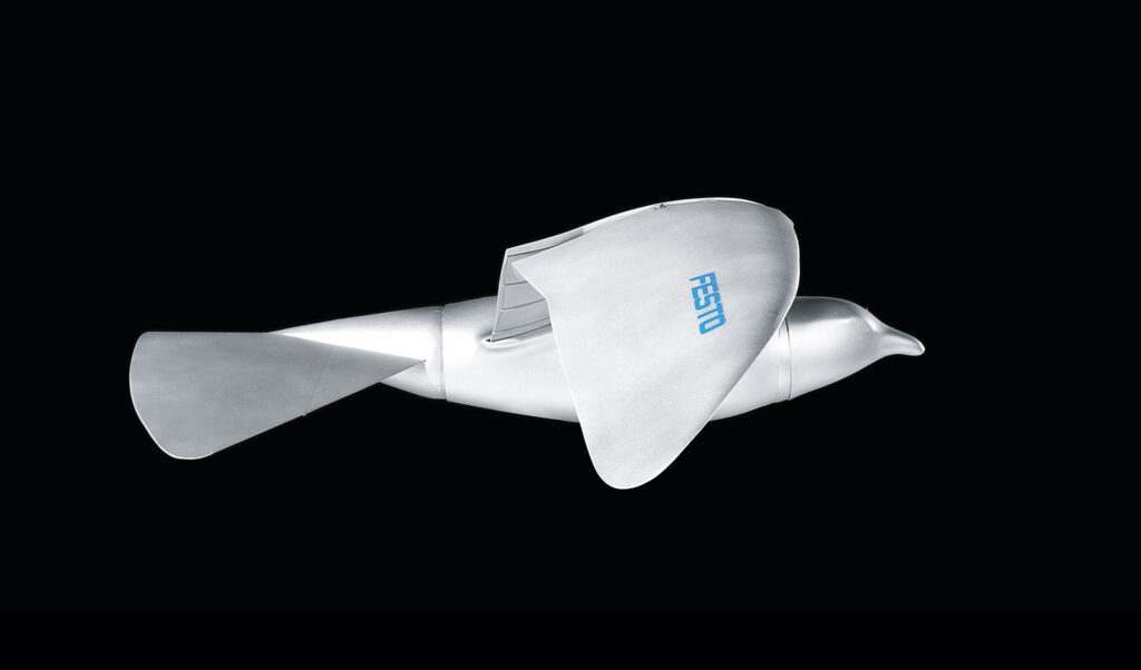
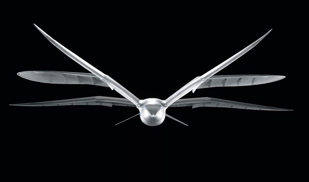
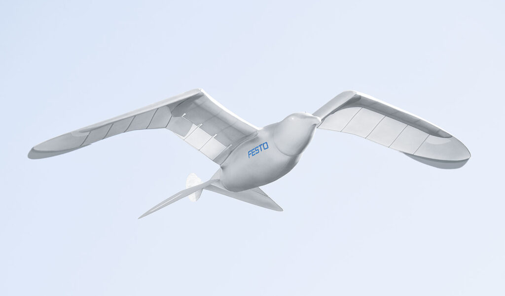
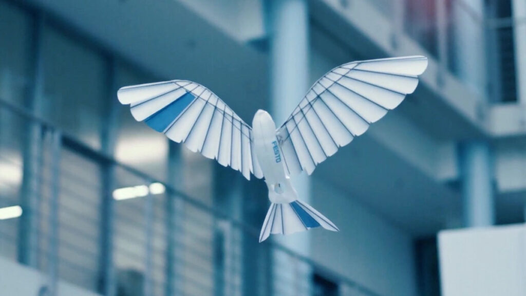
On 1 July 2020, Festo introduced the BionicSwift as their latest ultra light flying bionic robot that mimics how actual birds fly.
The BionicSwift, inspired by a Common Swift, measures 44.5 cm (17.5 in) long with a wingspan of 68 cm (26.7 in) and a weight of just 42 grams (1.5 ounces). It’s approximately a 2X scale-up of a Common Swift, but still a remarkably compact, yet complex flying machine with aerodynamic plumage that closely replicates the flight feathers on an actual Swift. The 2011 SmartBird was more than twice the physical size and ten times heavier.
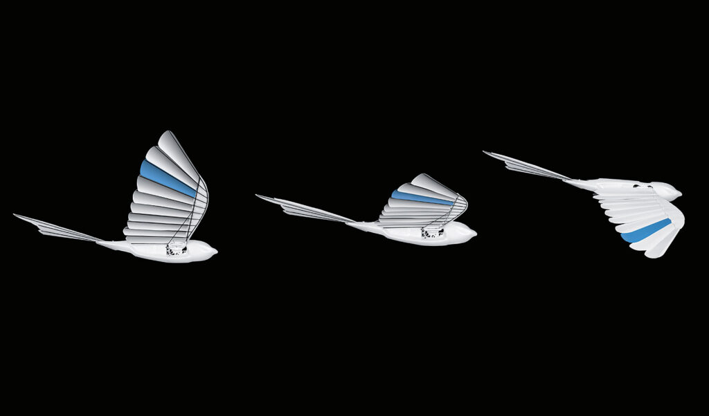
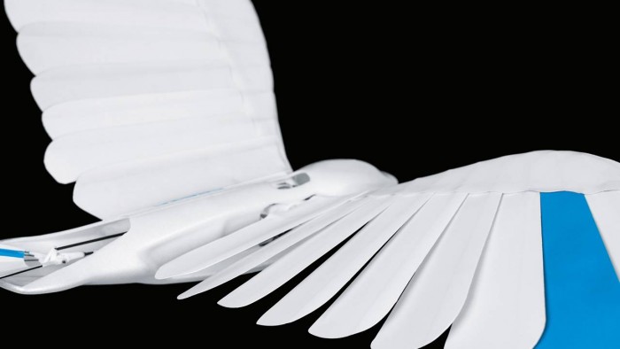
The BionicSwift is agile, nimble and can even fly loops and tight turns. Festo reports: “Due to this close-to-nature replica of the wings, the BionicSwifts have a better flight profile than previous wing-beating drives.” Compare the complex, feathered wing structure in the following Festo photos of the BionicSwift with the previous photos showing the simpler, solid wing structure of the 2011 SmartBird.
Source: All three BionicSwift photos from Festo
A BionicSwift can fly singly or in coordinated flight with a group of other BionicSwifts. Festo describes how this works: “Radio-based indoor GPS with ultra wideband technology (UWB) enables the coordinated and safe flying of the BionicSwifts. For this purpose, several radio modules are installed in one room. These anchors then locate each other and define the controlled airspace. Each robotic bird is also equipped with a radio marker. This sends signals to the anchors, which can then locate the exact position of the bird and send the collected data to a central master computer, which acts as a navigation system.” Flying time is about seven minutes per battery charge.
4. For more information about other Festo bionic creations:
I encourage you to visit the Festo BionIc Learning Network webpage at the following link and browse the resources available for the many intriguing projects. https://www.festo.com/group/en/cms/10156.htm
On this webpage you’ll find a series of links listed under the heading “More Projects,” which will introduce you to the wide range of Bionic Learning Network projects since 2006.
You also can watch the following YouTube short videos of Festo’s many bionic creations:
BionicFinWave (2018):replicates the swimming movements of sea creatures with undulating fins to create a unique fin drive system for an autonomous underwater vehicle: https://www.youtube.com/watch?v=fRNq55EbnZc
AirRay (2010): replicates the natural underwater movements of a Manta Ray in a larger-than-life, neutrally buoyant, ray-shaped airship with a flapping wing drive: https://www.youtube.com/watch?v=c3-wIICjAhE
AquaRay (2010): replicates the natural underwater movements of a Manta Ray in a full-size autonomous underwater vehicle with a flapping wing drive: https://www.youtube.com/watch?v=F4-6oNagIvk
AirPenguin (2009): replicates the natural underwater movements of a penguin in a larger-than-life, neutrally buoyant, penguin-shaped airship: https://www.youtube.com/watch?v=jPGgl5VH5go
AquaPenguin (2009): replicates the natural underwater movements of a penguin in a small penguin-sized autonomous underwater vehicle: https://www.youtube.com/watch?v=u8tfES8gImc
AirJelly (2008): replicates the natural underwater movements of a jelly fish in a larger-than-life, neutrally buoyant, jelly fish-shaped airship: https://www.youtube.com/watch?v=divLsTtA5vk
AquaJelly (2008): replicates the natural underwater movements of a jelly fish in a small, autonomous, peristaltic drive autonomous underwater vehicle that can operate in coordination with several other AquaJellies: https://www.youtube.com/watch?v=N-O8-N71Qcw
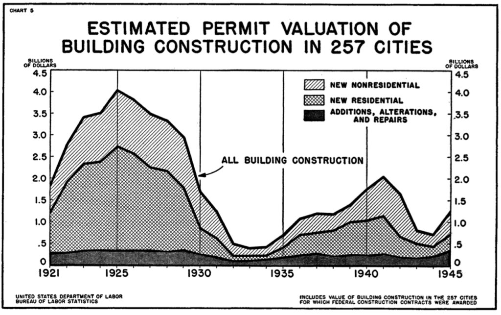
At the start of World War II (WW II), US home ownership had dropped to a low of 43.6% in 1940, largely as a consequence of the Great Depression and the weak US economy in its aftermath. During WW II, the War Production Board issued Conservation Order L-41 on 9 April 1942, placing all construction under rigid control. The order made it necessary for builders to obtain authorization from the War Production Board to begin construction costing more than certain thresholds during any continuous 12-month period. For residential construction, that limit was $500, with higher limits for business and agricultural construction. The impact of these factors on US residential construction between 1921 and 1945 is evident in the following chart, which shows the steep decline during the Great Depression and again after Order L-41 was issued.
Source: “Construction in the War Years – 1942 -45,” US Department of Labor, Bulletin No. 915
By the end of WW II, the US had an estimated 7.6 million troops overseas. The War Production Board revoked L-41 on 15 October 1945, five months after V-E (Victory in Europe) day on 8 May 1945 and six weeks after WW II ended when Japan formally surrendered on 2 September 1945. In the five months since V-E day, about three million soldiers had already returned to the US. After the war’s end, the US was faced with the impending return of several millions more veterans. Many in this huge group of veterans would be seeking to buy homes in housing markets that were not prepared for their arrival. Within the short span of a year after Order L-41 was revoked, the monthly volume of private housing expenditures increased fivefold. This was just the start of the post-war housing boom in the US.
In a March 1946 Popular Science magazine article entitled “Stopgap Housing,” the author, Hartley Howe, noted, “ Even if 1,200,000 permanent homes are now built every year – and the United States has never built even 1,000,000 in a single year – it will be 10 years before the whole nation is properly housed. Hence, temporary housing is imperative to stop that gap.” To provide some immediate relief, the Federal government made available many thousands of war surplus steel Quonset huts for temporary civilian housing.
Facing a different challenge in the immediate post-war period, many wartime industries had their contracts cut or cancelled and factory production idled. With the decline of military production, the U.S. aircraft industry sought other opportunities for employing their aluminum, steel and plastics fabrication experience in the post-war economy.
2. Post-WW II prefab aluminum and steel houses in the US
In the 2 September 1946 issue of Aviation News magazine, there was an article entitled “Aircraft Industry Will Make Aluminum Houses for Veterans,” that reported the following:
“Two and a half dozen aircraft manufacturers are expected soon to participate in the government’s prefabricated housing program.”
“Aircraft companies will concentrate on FHA (Federal Housing Administration) approved designs in aluminum and its combination with plywood and insulation, while other companies will build prefabs in steel and other materials. Designs will be furnished to the manufacturers.”
“Nearly all war-surplus aluminum sheet has been used up for roofing and siding in urgent building projects; practically none remains for the prefab program. Civilian Production Administration has received from FHA specifications for aluminum sheet and other materials to be manufactured, presumably under priorities. Most aluminum sheet for prefabs will be 12 to 20 gauge – .019 – .051 inch.”
In October 1946, Aviation News magazine reported, “The threatened battle over aluminum for housing, for airplanes and myriad postwar products in 1947 is not taken too seriously by the National Housing Agency, which is negotiating with aircraft companies to build prefabricated aluminum panel homes at an annual rate as high as 500,000.”……”Final approval by NHA engineers of the Lincoln Homes Corp. ‘waffle’ panel (aluminum skins over a honeycomb composite core) is one more step toward the decision by aircraft companies to enter the field.…..Aircraft company output of houses in 1947, if they come near meeting NHA proposals, would be greater than their production of airplanes, now estimated to be less than $1 billion for 1946.”
In late 1946, the FHA Administrator, Wilson Wyatt, suggested that the War Assets Administration (WAA), which was created in January 1946 to dispose of surplus government-owned property and materials, temporarily withhold surplus aircraft factories from lease or sale and give aircraft manufacturers preferred access to surplus wartime factories that could be converted for mass-production of houses. The WAA agreed.
Under the government program, the prefab house manufacturers would have been protected financially with FHA guarantees to cover 90% of costs, including a promise by Reconstruction Finance Corporation (RFC) to purchase any homes not sold.
Many aircraft manufacturers held initial discussions with the FHA, including: Douglas, McDonnell, Martin, Bell, Fairchild, Curtis-Wright, Consolidated-Vultee, North American, Goodyear and Ryan. Boeing did not enter those discussions and Douglas, McDonnell and Ryan exited early. In the end, most aircraft manufacturer were unwilling to commit themselves to the postwar prefab housing program, largely because of their concerns about disrupting their existing aircraft factory infrastructure based on uncertain market estimates of size and duration of the prefab housing market and lack of specific contract proposals from the FHA and NHA.
The original business case for the post-war aluminum and steel pre-fabricated houses was that they could be manufactured rapidly in large quantities and sold profitably at a price that was less than conventional wood-constructed homes. Moreover, the aircraft manufacturing companies restored some of the work volume lost after WW II ended and they were protected against the majority of their financial risk in prefab house manufacturing ventures.
Not surprisingly, building contractors and construction industry unions were against this program to mass-produce prefabricated homes in factories, since this would take business away from the construction industry. In many cities the unions would not allow their members to install prefabricated materials. Further complicating matters, local building codes and zoning ordnances were not necessarily compatible with the planned large-scale deployment of mass-produced, prefabricated homes.
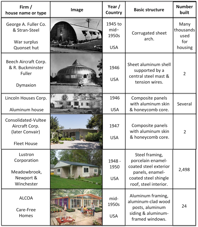
The optimistic prospects for manufacturing and erecting large numbers of prefabricated aluminum and steel homes in post-WW II USA never materialized. Rather than manufacturing hundreds of thousands of homes per year, the following five US manufacturers produced a total of less than 2,600 new aluminum and steel prefabricated houses in the decade following WW II: Beech Aircraft, Lincoln Houses Corp., Consolidated-Vultee, Lustron Corp. and Aluminum Company of America (Alcoa). In contrast, prefabricators offering more conventional houses produced a total of 37,200 units in 1946 and 37,400 in 1947. The market demand was there, but not for aluminum and steel prefabricated houses.
US post-WW II prefabricated aluminum and steel houses
These US manufacturers didn’t play a significant part in helping to solve the post-WW II housing shortage. Nonetheless, these aluminum and steel houses still stand as important examples of affordable houses that, under more favorable circumstances, could be mass-produced even today to help solve the chronic shortages of affordable housing in many urban and suburban areas in the US.
Some of the US post-WW II housing demand was met with stop gap, temporary housing using re-purposed, surplus wartime steel Quonset huts, military barracks, light-frame temporary family dwelling units, portable shelter units, trailers, and “demountable houses,” which were designed to be disassembled, moved and reassembled wherever needed. You can read more about post-WW II stop gap housing in the US in Hartley Howe’s March 1946 article in Popular Science (see link below).
The construction industry ramped up rapidly after WW II to help meet the housing demand with conventionally-constructed permanent houses, with many being built in large-scale housing tracts in rapidly expanding suburban areas. Between 1945 and 1952, the Veterans Administration reported that it had backed nearly 24 million home loans for WW II veterans. These veterans helped boost US home ownership from 43.6% in 1940 to 62% in 1960.
Two post-WW II US prefabricated aluminum and steel houses have been restored and are on public display in the following museums:
In addition, you can visit several WW II Quonset huts at the Seabees Museum and Memorial Park in North Kingstown, Rhode Island. None are outfitted like a post-WW II civilian apartment. The museum website is here: https://www.seabeesmuseum.com
You’ll find more information in my articles on specific US post-WW II prefabricated aluminum and steel houses at the following links:
3. Post-WW II prefab aluminum and steel houses in the UK
By the end of WW II in Europe (V-E Day is 8 May 1945), the UK faced a severe housing shortage as their military forces returned home to a country that had lost about 450,000 homes to wartime damage.
On 26 March 1944, Winston Churchill made an important speech promising that the UK would manufacture 500,000 prefabricated homes to address the impending housing shortage. Later in the year, the Parliament passed the Housing (Temporary Accommodation) Act, 1944, charging the Ministry of Reconstruction with developing solutions for the impending housing shortage and delivering 300,000 units within 10 years, with a budget of £150 million.
The Act provided several strategies, including the construction of temporary, prefabricated housing with a planned life of up to 10 years. The Temporary Housing Program (THP) was officially known as the Emergency Factory Made (EFM) housing program. Common standards developed by the Ministry of Works (MoW) required that all EFM prefabricated units have certain characteristics, including:
Minimum floor space of 635 square feet (59 m2)
Maximum width of prefabricated modules of 7.5 feet (2.3 m) to enable transportation by road throughout the country
Implement the MoW’s concept of a “service unit,” which placed the kitchen and bathroom back-to-back to simplify routing plumbing and electrical lines and to facilitate factory manufacture of the unit.
Factory painted, with “magnolia” (yellow-white) as the primary color and gloss green as the trim color.
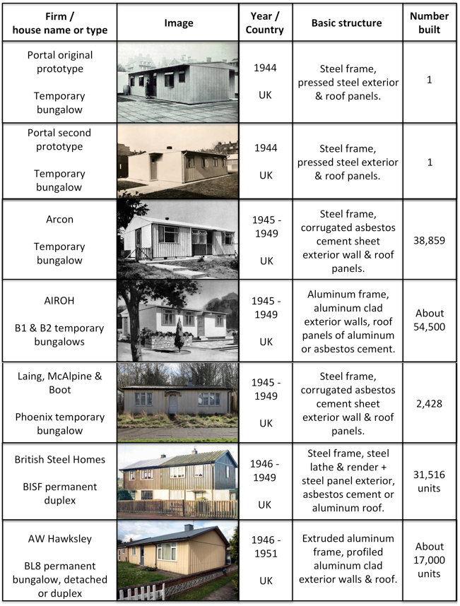
In 1944, the UK Ministry of Works held a public display at the Tate Gallery in London of five types of prefabricated temporary houses.
The original Portal all-steel prototype bungalow
The AIROH (Aircraft Industries Research Organization on Housing) aluminum bungalow, made from surplus aircraft material.
The Arcon steel-framed bungalow with asbestos concrete panels. This deign was adapted from the all-steel Portal prototype.
Two timber-framed prefab designs, the Tarran and the Uni-Seco
This popular display was held again in 1945 in London.
Supply chain issues slowed the start of the EFM program. The all-steel Portal was abandoned in August 1945 due to a steel shortage. In mid-1946, a wood shortage affected other prefab manufacturers. Both the AIROH and Arcon prefab houses were faced with unexpected manufacturing and construction cost increases, making these temporary bungalows more expensive to build than conventionally constructed wood and brick houses.
Under a Lend-Lease Program announced in February 1945, the US agreed to supply the UK with US-built, wood frame prefabricated bungalows known as the UK 100. The initial offer was for 30,000 units, which subsequently was reduced to 8,000. This Lend-Lease agreement came to an end in August 1945 as the UK started to ramp up its own production of prefabricated houses. The first US-built UK 100 prefabs arrived in late May/early June 1945.
The UK’s post-war housing reconstruction program was quite successful, delivering about 1.2 million new houses between 1945 and 1951. During this reconstruction period, 156,623 temporary prefabricated homes of all types were delivered under the EFM program, which ended in 1949, providing housing for about a half million people. Over 92,800 of these were temporary aluminum and steel bungalows. The AIROH aluminum bungalow was the most popular EFM model, followed by the Arcon steel frame bungalow and then the wood frame Uni-Seco. In addition, more than 48,000 permanent aluminum and steel prefabricated houses were built by AW Hawksley and BISF during that period.
In comparison to the very small number of post-war aluminum and steel prefabricated houses built in the US, the post-war production of aluminum and steel prefabs in the UK was very successful.
UK post-WW II prefabricated aluminum and steel houses
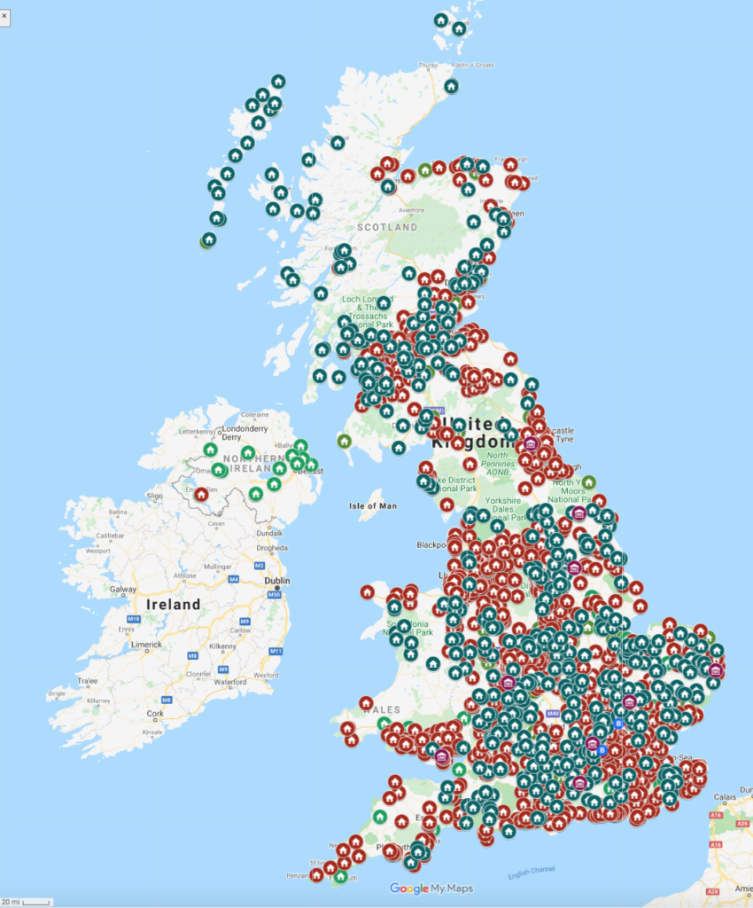
In a 25 June 2018 article in the Manchester Evening News, author Chris Osuh reported that, “It’s thought that between 6 or 7,000 of the post-war prefabs remain in the UK…..” The Prefab Museum maintains a consolidated interactive map of known post-WW II prefab house locations in the UK at the following link: https://www.prefabmuseum.uk/content/history/map
Screenshot of the Prefab Museum’s interactive map (not including the prefabs in the Shetlands, which are off the top of this screenshot).
In the UK, Grade II status means that a structure is nationally important and of special interest. Only a few post-war temporary prefabs have been granted the status as Grade II listed properties:
In an estate of Phoenix steel frame bungalows built in 1945 on Wake Green Road, Moseley, Birmingham, 16 of 17 homes were granted Grade II status in 1998.
Six Uni-Seco wood frame bungalows built in 1945 – 46 in the Excalibur Estate, Lewisham, London were granted Grade II status in 2009. At that time, Excalibur Estates had the largest number of WW II prefabs in the UK: 187 total, of several types.
Several post-war temporary prefabs are preserved at museums in the UK and are available to visit.
St. Fagans National Museum of History in Cardiff, South Wales: An AIROH B2 originally built near Cardiff in 1947 was dismantled and moved to its current museum site in 1998 and opened to the public in 2001. You can see this AIROH B2 here: https://museum.wales/stfagans/buildings/prefab/
Chiltern Open Air Museum (COAM) in Chalfont St. Giles, Buckinghamshire: Their collection includes a wood frame Universal House Mark 3 prefab manufactured by Universal Housing Company of Rickmansworth, Hertfordshire. This prefab was built in 1947 in the Finch Lane Estate in Amersham. You can see the “Amersham Prefab” here: https://www.coam.org.uk/museum-buckinghamshire/historic-buildings/amersham-prefab/
I think the Prefab Museum is best source for information on UK post-WW II prefabs. When it was created in March 2014 by Elisabeth Blanchet (author of several books and articles on UK prefabs) and Jane Hearn, the Prefab Museum had its home in a vacant prefab on the Excalibur Estate in south London. After a fire in October 2014, the physical museum closed but has continued its mission to collect and record memories, photographs and memorabilia, which are presented online via the Prefab Museum’s website at the following link: https://www.prefabmuseum.uk
You’ll find more information in my articles on specific UK post-WW II prefabricated aluminum and steel houses at the following links:
4. Post-WW II prefab aluminum and steel houses in France
At the end of WW II, France, like the UK, had a severe housing shortage due to the great number of houses and apartments damaged or destroyed during the war years, the lack of new construction during that period, and material shortages to support new construction after the war.
To help relieve some of the housing shortage in 1945, the French Reconstruction and Urbanism Minister, Jean Monnet, purchased the 8,000 UK 100 prefabricated houses that the UK had acquired from the US under a Lend-Lease agreement. These were erected in the Hauts de France (near Belgium), Normandy and Brittany, where many are still in use today.
The Ministry of Reconstruction and Town Planning established requirements for temporary housing for people displaced by the war. Among the initial solutions sought were prefabricated dwellings measuring 6 x 6 meters (19.6 x 19.6 feet); later enlarged to 6 × 9 meters (19.6 x 29.5 feet).
About 154,000 temporary houses (the French called then “baraques”), in many different designs, were erected in France in the post-war years, primarily in the north-west of France from Dunkirk to Saint-Nazaire. Many were imported from Sweden, Finland, Switzerland, Austria and Canada.
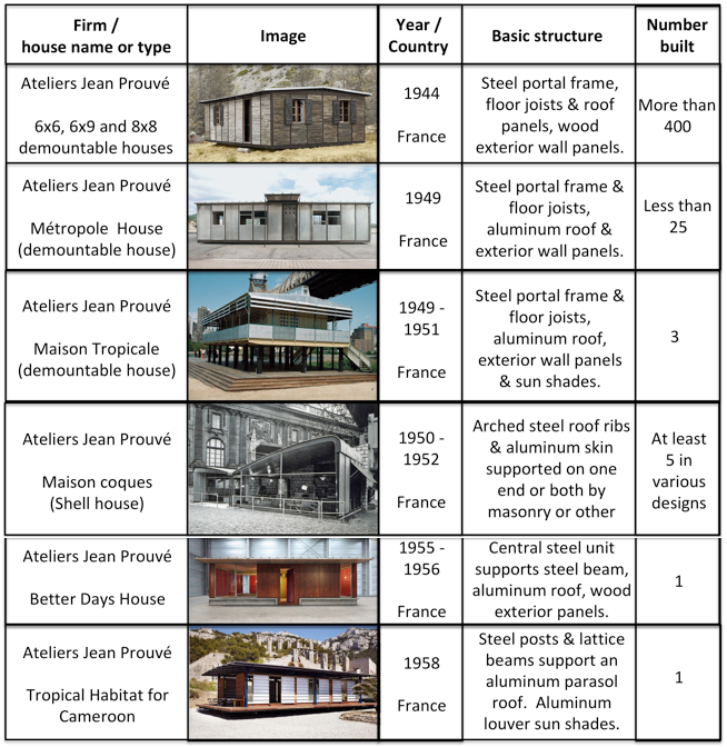
The primary proponent of French domestic prefabricated aluminum and steel house manufacturing was Jean Prouvé, who offered a novel solution for a “demountable house,” which could be easily erected and later “demounted” and moved elsewhere if needed. A steel gantry-like “portal frame” was the load-bearing structure of the house, with the roof usually made of aluminum, and the exterior panels made of wood, aluminum or composite material. Many of these were manufactured in the size ranges requested by Ministry of Reconstruction. During a visit to Prouvé’s Maxéville workshop in 1949, Eugène Claudius-Petit, then the Minister of Reconstruction and Urbanism, expressed his determination to encourage the industrial production of “newly conceived (prefabricated) economical housing.”
French post-WW II prefabricated aluminum and steel houses
Today, many of Prouvé’s demountable aluminum and steel houses are preserved by architecture and art collectors Patrick Seguin (Galerie Patrick Seguin) and Éric Touchaleaume (Galerie 54 and la Friche l’Escalette). Ten of Prouvé’s Standard Houses and four of his Maison coques-style houses built between 1949 – 1952 are residences in the small development known as Cité “Sans souci,” in the Paris suburbs of Muedon.
Prouvé’s 1954 personal residence and his relocated 1946 workshop are open to visitors from the first weekend in June to the last weekend in September in Nancy, France. The Musée des Beaux-Arts de Nancy has one of the largest public collections of objects made by Prouvé.
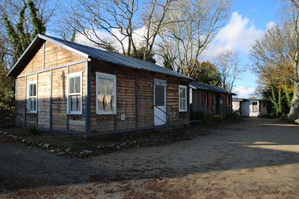
Author Elisabeth Blanchet reports that the museum “Mémoire de Soye has managed to rebuild three different ‘baraques’: a UK 100, a French one and a Canadian one. They are refurbished with furniture from the war and immediate post-war era. Mémoire de Soye is the only museum in France where you can visit post-war prefabs.” The museum is located in Lorient, Brittany. Their website (in French) is here: http://www.soye.org
The three wood frame ‘baraques’ at Mémoire de Soye. Source: Elisabeth Blanchet via the Prefab Museum (UK)
In the U.S., the post-war mass production of prefabricated aluminum and steel houses never materialized. Lustron was the largest manufacturer with 2,498 houses. In the UK, over 92,800 prefabricated aluminum and steel temporary bungalows were built as part of the post-war building boom that delivered a total of 156,623 prefabricated temporary houses of all types between 1945 and 1949, when the program ended. In France, hundreds of prefabricated aluminum and steel houses were built after WW II, with many being used initially as temporary housing for people displaced by the war. Opportunities for mass production of such houses did not develop in France.
The lack of success in the U.S. arose from several factors, including:
High up-front cost to establish a mass-production line for prefabricated housing, even in a big, surplus wartime factory that was available to the house manufacturer on good financial terms.
Immature supply chain to support a house manufacturing factory (i.e., different suppliers are needed than for the former aircraft factory).
Ineffective sales, distribution and delivery infrastructure for the manufactured houses.
Diverse, unprepared local building codes and zoning ordnances stood in the way of siting and erecting standard design, non-conventional prefab homes.
Opposition from construction unions and workers that did not want to lose work to factory-produced homes.
Only one manufacturer, Lustron, produced prefab houses in significant numbers and potentially benefitted from the economics of mass production. The other manufacturers produced in such small quantities that they could not make the transition from artisanal production to mass production.
Manufacturing cost increases reduced or eliminated the initial price advantage predicted for the prefabricated aluminum and steel houses, even for Lustron. They could not compete on price with comparable conventionally constructed houses.
In Lustron’s case, charges of corporate corruption led the Reconstruction Finance Corporation to foreclose on Lustron’s loans, forcing the firm into an early bankruptcy.
From these post-WW II lessons learned, and with the renewed interest in “tiny homes”, it seems that there should be a business case for a modern, scalable, smart factory for the low-cost mass-production of durable prefabricated houses manufactured from aluminum, steel, and/or other materials. These prefabricated houses could be modestly-sized, modern, attractive, energy efficient (LEED-certified), and customizable to a degree while respecting a basic standard design. These houses should be designed for mass production and siting on small lots in urban and suburban areas. I believe that there is a large market in the U.S. for this type of low-price housing, particularly as a means to address the chronic affordable housing shortages in many urban and suburban areas. However, there still are great obstacles to be overcome, especially where construction industry labor unions are likely to stand in the way and, in California, where nobody will want a modest prefabricated house sited next to their McMansion.
You can download a pdf copy of this post, not including the individual articles, here:
Blaine Stubblefield, “Aircraft Industry Will Make Aluminum Houses for Veterans,” Aviation News, Vol. 6, No. 10, 2 September 1946 (available in the Aviation Week & Space Technology magazine online archive)
“Battle for Aluminum Discounted by NHA,” Aviation News magazine, p. 22, 14 October 1946 (available in the Aviation Week & Space Technology magazine online archive)
Nicole C. Rudolph, “At Home in Postwar France – Modern Mass Housing and the Right to Comfort,” Berghahn Monographs in French Studies (Book 14), Berghahn Books, March 2015, ISBN-13: 978-1782385875. The introduction to this book is available online at the following link: https://berghahnbooks.com/downloads/intros/RudolphAt_intro.pdf
Kenny Cupers, “The Social Project: Housing Postwar France,” University Of Minnesota Press, May 2014, ISBN-13: 978-0816689651
In an effort to improve the generating and economic performance of wind turbines, manufacturers have been designing and building increasingly larger machines. Practical limits on transporting these very long and heavy components between the factories and the installation sites may limit the scale of the wind turbines selected for some applications and may require novel solutions that affect component design, factory siting and choice of transportation mode. In this post, we’ll take a look at these issues.
1. The latest generation of wind turbines
1.1 GE Cypress platform
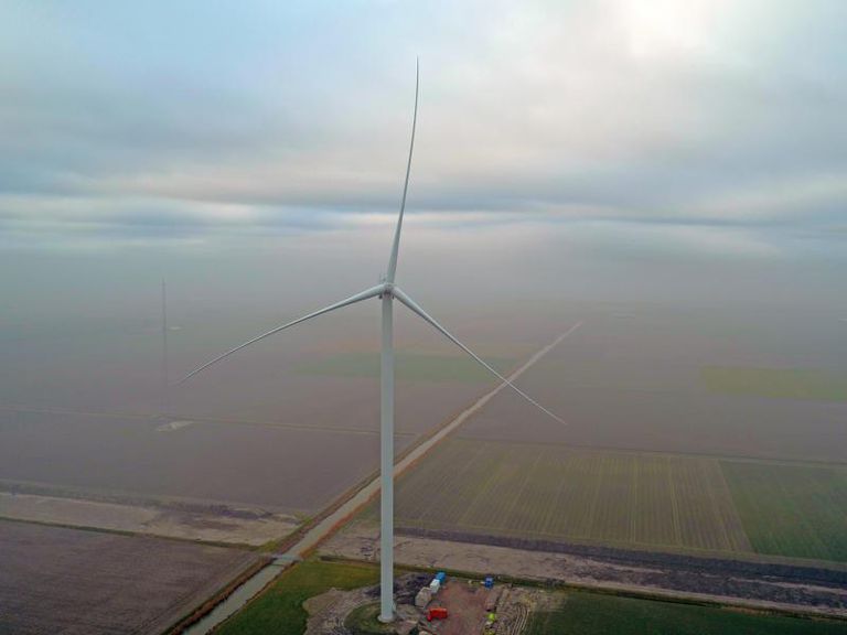
On 13 March 2019, General Electric (GE) Renewable Energy announced that its largest onshore wind turbine prototype, named Cypress, started commercial operation in the Netherlands. Unlike other large wind turbines, the prototype Cypress composite turbine blades come in two pieces and are assembled on site. Cypress was announced in September 2017 and construction of the prototype began in 2018.
The 5.3 MW Cypress prototype wind turbine. Source: GE
The Cypress 5.3-158 prototype has a nominal generating capacity of 5.3 MW. A smaller Cypress 4.8-158 (with a 4.8 MW rating) is currently under production at GE’s Salzbergen, Germany factory, and it is expected to be commissioned by the end of the 2019. Both have a rotor diameter of 158 meters (518.3 ft).
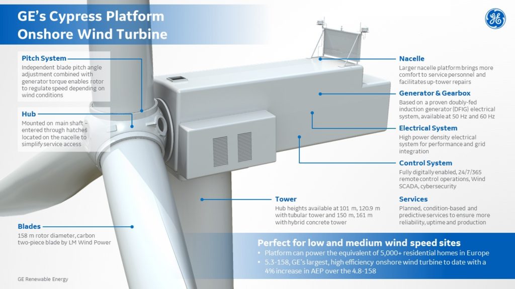
Anatomy of a GE Cypress wind turbine. Source: GE
GE reports that the Cypress platform is “powered by a revolutionary two-piece blade design that makes it possible to use larger rotors and site the turbines in a wider variety of locations. The Annual Electricity Production (AEP) improvements from the longer rotors help to drive down Levelized Cost of Electricity (LCOE), and the proprietary blade design allows these larger turbines to be installed in locations that were previously inaccessible.” Site accessibility can be limited by the practicality of ground transportation of single-piece blades that can be nearly 91.4 meters (300 feet) long.
1.2 GE LM 88.4 P, the longest one-piece rotor blade in the world
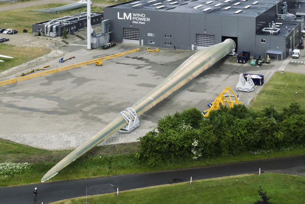
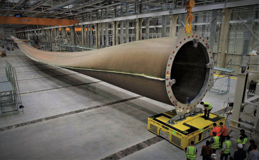
LM Wind Power, a GE Renewable Energy business, has delivered the longest one-piece wind turbine blades built to date, the LM 88.4 P, which measure 88.4 meters (290 ft) long. Three of these giant blades are installed onshore in Denmark on an Adwen’s AD 8-180 wind turbine, which has an 8 MW nominal generating capacity and a 180 meter (590.5 ft) rotor diameter. You can get a sense of the size of an LM 88.4 P in the following photo showing a rotor blade leaving the factory.
88.4 meter (290 ft) LM 88.4 P wind turbine rotor blade leaving the factory. Source: LM Wind Power
1.3 GE Haliade-X platform
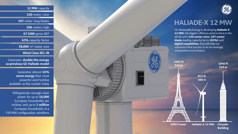
GE is developing an even larger wind turbine platform, the Haliade X, which will become the world’s largest wind turbine when it is completed. This 12 MW platform, which is being developed primarily for offshore wind farms, features 107 meter (351 ft) long one-piece blades and a 220 meter (722 ft) rotor diameter. The first prototype unit will be installed onshore near Rotterdam, Netherlands, where it will stand 259 meters (850 ft) tall, from the base of the tower to the top of the blade sweep.
Anatomy of a GE 12 MW Haliade-X wind turbine. Source: GE
Construction of the prototype Haliade-X wind turbine began in 2019. The first blade is shown in the photo below. After securing a “type certificate” for the Haliade-X platform, GE plans to start selling this wind turbine commercially as early as 2021. The near-term market focus appears to be new wind turbines sited in the North Sea.
The first 107 meter (351 ft) Haliade-X blade at the factory in Cherbourg, France. Source GE Renewable Energy
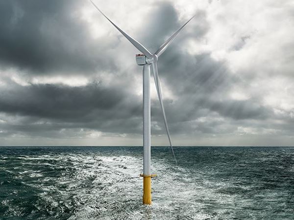
1.4 Siemens Gamesa SG 10.0-193 DD platform
In January 2019, Siemens Gamesa launched its next generation (Generation V) of very large offshore wind turbines, the SG 10.0-193 DD, which has a nominal generator rating of 10 MW, blade length of 94 meters (308 ft) and a rotor diameter of 193 meters (633 ft). The nacelle housing the wind turbine hub and generator weighs up to 400 tons.
The 10 MW Siemens SG 10.0-193 DD. Source: Siemens Gamesa
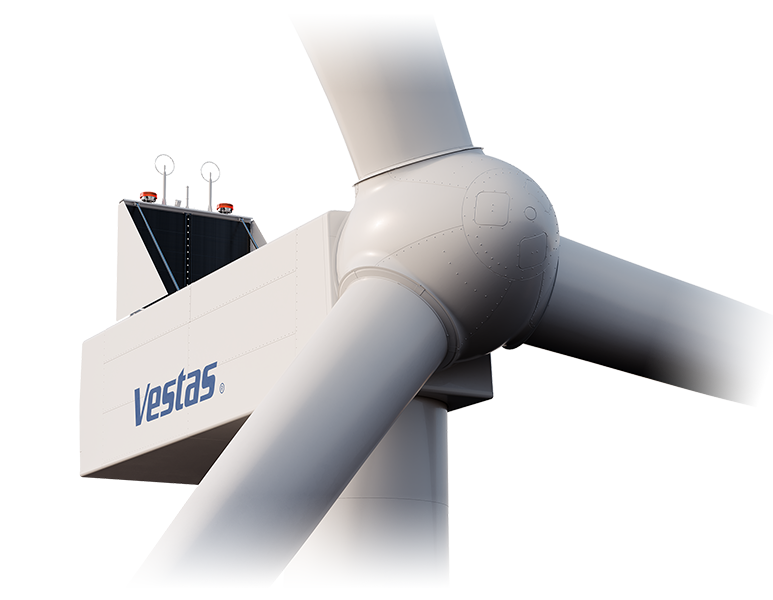
1.5 Vestas EnVestusTM platform
The EnVestusTM platform, which was introduced in 2019, is Vestas’ next generation in its evolution of wind turbines. The V162-5.6 MW has a rotor diameter of 162 meters (531 ft), which is the largest rotor size offered in the current EnVestusTM product portfolio. Various tower sizes are offered, with hub heights up to 166 meters (545 ft). With this tallest tower, the blade sweep of a V162-5.6 MW wind turbine reaches a height of 247 meters (810 ft).
V162-5.6 MW nacelle. Source: Vestas
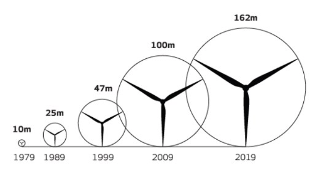
The trend in Vestas wind turbine maximum rotor size is evident in the following diagram. In comparison, the largest GE wind turbine, the Haliade-X will have a rotor diameter of 220 meter (722 ft), and the largest Siemens Generation V wind turbine will have a rotor diameter of 193 meters (633 ft).
2. Transporting very large wind turbine components
The manufacturer’s efforts to improve wind turbine generating and economic performance has resulted in increasingly larger machine components, which are challenging the limits of today’s transportation infrastructure as the components are moved from the manufacturer’s factories to the installation sites. Here, we’ll look at the various ways these large components are transported.
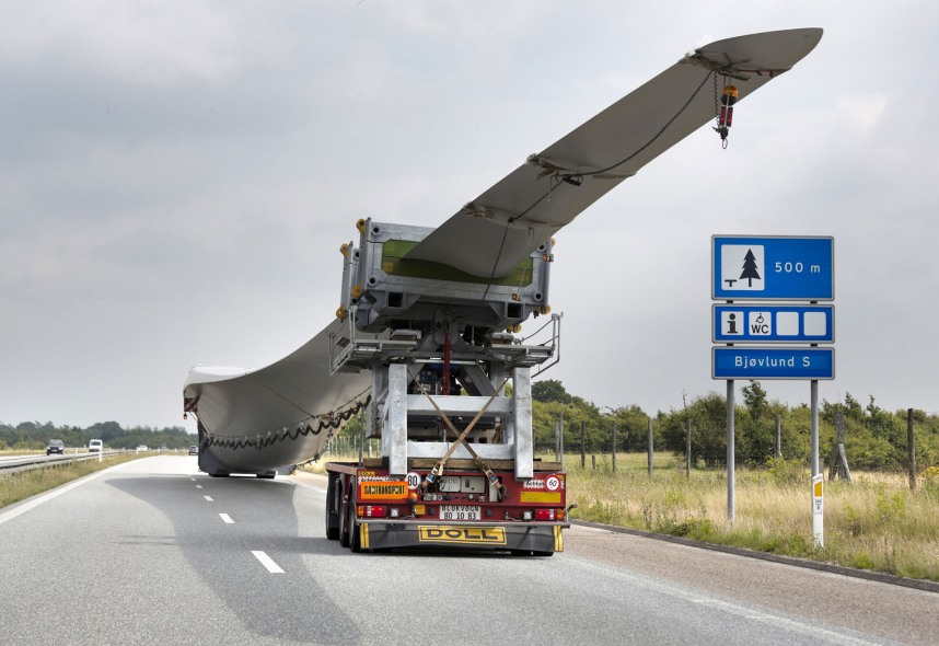
2.1 Transportation of wind turbine components by land
Popular Mechanics reported that, “Moving long turbine blades is such a logistical nightmare that the companies involved sometimes resort to building new roads for the sole purpose of moving blades.” Transporting wind turbine tower and nacelle components can be equally challenging. You’ll find an interesting assessment by CGS Labs of the challenges of wind farm ground transportation planning at the following link: https://www.cgs-labs.com/Software/Autopath/Articles/Windturbinetransport.aspx
As noted previously, the GE one-piece LM 88.4 P, which is 88.4 meters (290 ft) long, is the longest wind turbine rotor blade currently in service. You can watch a short video of a single LM 88.4 P blade being transported 218 km (135 miles) to the construction site at the following link. Total transport weight was 60 tons (120,000 lb, 54,431 kg). https://www.lmwindpower.com/en/products-and-services/blade-types/longest-blade-in-the-world
88.4 meter (290 ft) LM 88.4 P wind turbine blade during transport. Source: Screenshot from LM Wind Power video
Specialized trucks are employed to negotiate existing roads. Examples of difficult transportation situations are shown in the following photos.
Siemens 75 m (243 ft) rotor blade was transported 320 km (199 miles) by road. Source: utilities-me.com, 14 Aug 2012Making a sharp turn with a specialized truck for transporting a Vestas V117 57.5 meter (189 ft) wind turbine blade. Source: CNN.com, 5 October 2017
Specially-designed trucks move 52.4 meter (172 foot) long wind turbine blades on narrow roads on Baoding Mountain in China. Source: Business Insider, 2 Mar 2017
2.2. Transportation of wind turbine components by sea
The single-piece blades for the GE Haliade X wind turbine are so long that they couldn’t be transported by land from GE’s existing factories. Therefore, a new LM Wind Power blade factory for the offshore wind market was built in Cherbourg, France, on the banks of the English Channel in Normandy. This factory can load blades directly onto ships for delivery to offshore wind turbine sites.
GE wind turbine blades shipped by sea. Source: LM Wind Power
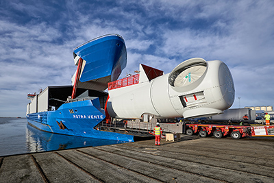
In December 2016, Siemens Gamesa reported, “When our new factories in Hull, England and Cuxhaven, Germany become fully operational, and both Ro-Ro (“roll-on, roll-off”) vessels are in service as interconnection of our manufacturing and installation network, we expect savings of 15-20 percent in logistics costs compared to current transport procedures. This is another important contributor reducing the cost of electricity from offshore wind.”
The Hull, UK rotor blade factory, located at the Alexandra Docks on the harbor, was completed in 2016. The Esbjerg, Denmark factory also is located on the harbor with direct access to shipping.
In 2018, Siemens Gamesa opened its modern factory in Cuxhaven, Germany for manufacturing offshore wind turbine nacelles. These three Siemens wind turbine factories have direct Ro-Ro access to shipping.In November 2016, Siemens commissioned its first specialized Ro-Ro transport vessel, the Rotra Vente. This ship is designed to transport multiple heavy nacelles, or up to nine tower sections, or three to four sets of rotor blades, depending on what else is being transported. A second specialized Ro-Ro transport vessel, the Rotra Mare, was commissioned in the spring of 2017 to transport tower sections and up to 12 rotor blades. These specialized transport vessels link the Siemens factories and transport the finished wind turbine components to the respective installation harbor.
The Rotra Vente provides Ro-Ro access for large Siemens wind turbine components. Source: Siemens
2.3. Transportation of wind turbine components by airship
For more than two decades, there has been significant interest in the use of modern lighter-than-air craft and hybrid airships in a variety of heavy-lift roles. One such role is the transportation of large wind turbine components. Airships offer the potential to transport the components quickly between factory and installation site without the constraints of current ground and sea transportation networks.
Three examples of airship concepts for transporting wind turbine components are described below.
Hybrid airships
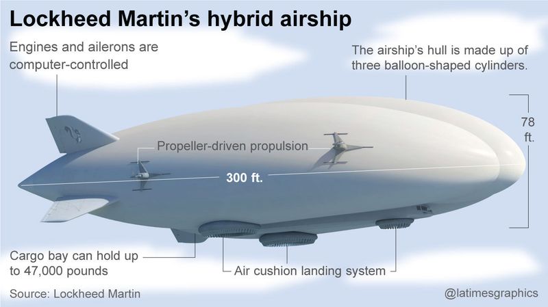
In 2017, Lockheed-Martin proposed its LMH-1 hybrid airship to deliver large wind turbine components weighing up to 23.5 tons (47,000 lb; 21,000 kg). The LMH-1 will be capable of flying 1,400 nautical miles (2,593 km) at a speed of about 70 knots (80 mph, 129 kph). Lockheed-Martin is expected to fly the commercial prototype of its LMH-1 hybrid airship in 2019. You can read Lockheed-Martin’s proposal for airship transport of wind turbine components here: https://www.lockheedmartin.com/content/dam/lockheed-martin/eo/documents/webt/transporting-wind-turbine-blades.pdf
This type of airship conducts short takeoff and landing (STOL) operations when transporting heavy loads, but can operate from relatively unprepared sites. When off-loading heavy cargo, this airship must take on ballast at the landing site.
After LMH-1, Lockheed Martin has plans to build a medium-size (90 ton cargo) hybrid airship that would be more competitive with trucking and rail transport.
Anatomy of the LMH-1 hybrid airship. Source: Lockheed Martin
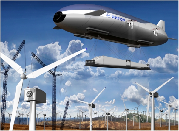
Variable buoyancy airships
In January 2013, Worldwide Aeros Corp. (Aeros), located in Montebello, CA, conducted the first “float test” of their Dragon Dream variable buoyancy airship. More recently, Aeros has reported that they are working on the first commercial prototype of a larger variable buoyancy airship to be known as the ML866 / Aeroscraft Gen 2, which will be 169 meters (555 ft) long. This airship is being designed with great range (3,100 nautical miles; 5,741 km) and a cruise speed of 100 – 120 knots. The ML866 will have a cargo capacity of 66 tons (132,000 lb; 59,874 kg). The first ML866 prototype is not expected to fly before the early 2020s.
This type of airship is designed to conduct vertical takeoff and landing (VTOL) operations with a full cargo load, and can hover above a site and take on or deliver cargo without landing and without transferring ballast to/from the ground site.
Concept drawing of an Aeroscraft variable buoyancy airship delivering wind turbine blades to a site. Source: Worldwide Aeros Corp.
Semi-rigid airships
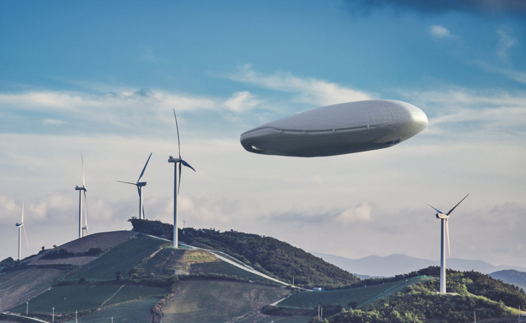
The KNARR initiative is a project created by two Danish design architects, Rune Kirt and Mads Thomsen to design a freight solution using modern airships to reduce the cost and energy consumption of today’s wind turbine freight business and make the logistics for wind turbine freight simpler and more efficient. Their main point is that transportation and installation costs can be up to 60% of the total cost of a new wind turbine, and these activities have a large carbon footprint. Their solution is a modern airship that is designed specifically for transporting very large and heavy wind turbine components directly from the manufacturer’s factory to the installation site. For their work, they were awarded both the Danish Design Center’s Special Prize and the International Core77 Design “Speculative Concept.”. You can read more about the firm, KIRT x THOMSEN aps, and the KNARR initiative here: https://www.kirt-thomsen.com/case10_airship-knarr
The KNARR semi-rigid airship would be 360 meters (1,181 ft) long and would carry the wind turbine components in a large internal cargo bay. This type of airship is designed to conduct VTOL operations with a full cargo load. When off-loading heavy cargo, this airship must take on ballast at the landing site.
The KNARR airship is a concept only. No prototype is being built at this time. You can view a short video defining the wind turbine transport application of KNARR airship here: https://vimeo.com/21023051
Concept drawing of a KNARR airships it lifts off after making a delivery. Source: https://www.kirt-thomsen.com/Concept drawing of a KNARR airship flying over a wind farm. Source: https://www.kirt-thomsen.com/
3. Conclusions
The scale of the latest generation of wind turbines, particularly the GE LM 88.4 P, which measure 88.4 meters (290 ft) long, is approaching the limits of existing ground transportation infrastructure to handle delivery of such blades from the factory to the installation site. GE’s introduction of two-piece blades on their new Cypress platform will significantly improve the logistics for delivering these large blades to installation sites.
Siemens’ practice of siting its wind turbine component factories with ready access to Ro-Ro shipping at an adjacent port facility greatly reduces the complexity of delivering large components to a port near an installation site. GE has adopted the same approach with their latest factory for manufacturing the Haliad-X rotor blades in Cherbourg, France, on the English Channel.
Airships could revolutionize the transportation of large, heavy items such as wind turbine components. However, the earliest likely candidate, the Lockheed Martin LMH-1 will not be available until the early 2020s and will be limited to a maximum load of 23.5 tons (47,000 lb; 21,000 kg). It seems unlikely that larger heavy-lift airships will be introduced before about 2025.
So, in the meantime, we’ll see the largest wind turbines being installed in offshore sites. For onshore sites, we’ll see more creative ground transportation schemes, and, probably, a broader introduction of multi-part rotor blades.
4. Recommended additional reading on wind turbines:
This 3 August 2016 post was replaced on 15 June 2020 with my updated and expanded post with the same title, “Post-World War II Prefabricated Aluminum and Steel Houses and Their Relevance Today,” which is available at the following link:
The updated and expanded resource document provides a brief overview of the post-WW II housing crisis in the US, UK and France, and the efforts in these nations to help resolve the housing crisis with mass-produced, prefabricated aluminum and steel houses. It also provides links to 13 individual, downloadable articles I prepared on specific types of post-WW II prefabricated aluminum and steel houses manufactured in the US, UK and France.
I hope you’ll find the new post to be informative, useful and different from any other single source on the subject.
The U.S firm Correlated Magnetics Research (CMR), Huntsville, AL, invented and is the sole manufacturer of Polymagnets®, which are precision-tailored magnets that enhance existing and new products with specific behaviors that go far beyond the simple attract-and-repel behavior of common magnets. Polymagnets have been granted over 100 patents, all held by CMR. You can visit their website at the following link:
“Essentially programmable magnets, Polymagnets are the first fundamental advance in magnets in 180 years, since the introduction of electromagnets. With Polymagnets, new products can have softer ‘feel’ or snappier or crisper closing or opening behavior, and may be given the sensation of a spring or latch”.
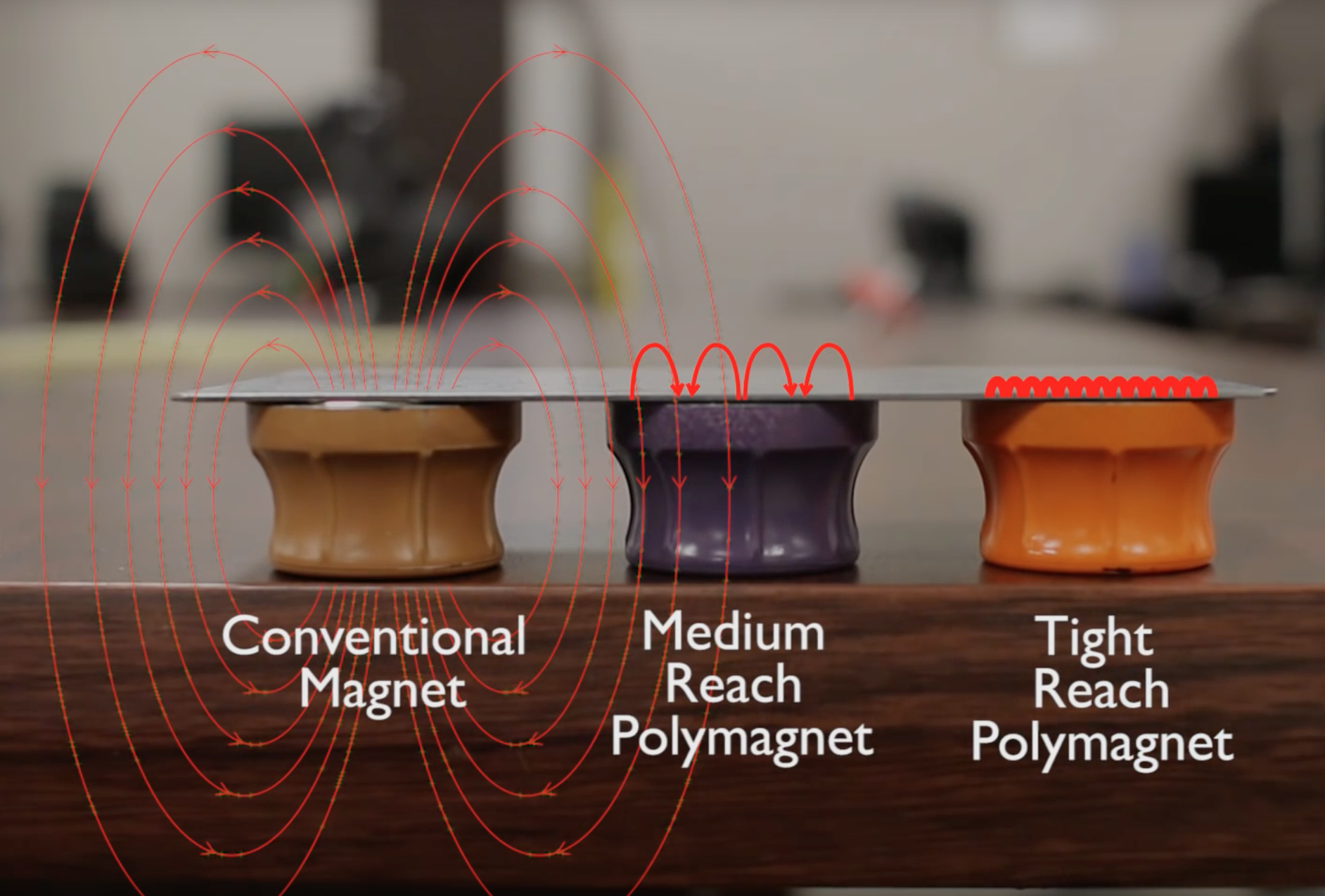
On a conventional magnet, there is a North (N) pole on one surface and a South (S) pole on the opposite surface. Magnetic field lines flow around the magnetic from pole to pole. On a Polymagnet®, many small, polarized (N or S) magnetic pixels (“maxels”) are manufactured by printing in a desired pattern on the same surface. The magnetic field lines are completed between the maxels on that surface, resulting in a very compact, strong magnetic field. This basic concept is shown in the following figure.
The mechanical 3-D behavior of a Polymagnet® is determined by the pattern and strength of the maxels embedded on the surface of the magnet. These customizable behaviors include spring, latch, shear, align, snap, torque, hold, twist, soften and release. The very compact magnetic field reduces magnetic interference with other equipment, opening new applications for Polymagnets® where a conventional magnet wouldn’t be suitable.
The above figure is a screenshot from the Smarter Every Day 153 video, which you can view at the following link. Thanks to Mike Spaeth for sending me this is a 10-minute video, which I think you will enjoy.
More information on Polymagnet® technology, including short videos that demonstrate different mechanical behaviors, and a series of downloadable white papers, is available at the following link.
This is remarkable new technology in search of novel applications. Many practical applications are identified on the Polymagnet® website. What are your ideas?
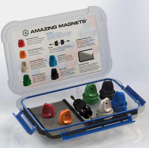
If you really want to look into this technology, you can buy a Polymagnet® demonstration kit at the following links:
In a 31 December 2015 post, I discussed the “U.S. Commercial Space Launch Competitiveness Act,” which was signed into law on 25 November 2015 and established, among other things, the legal basis for asteroid mining. I also identified the firm Planetary Resources (http://www.planetaryresources.com/ – home-intro) as one of the firms having a business interest in asteroid prospecting.
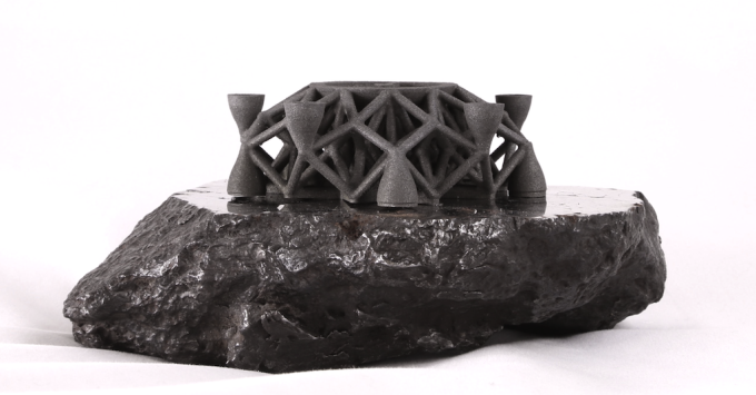
Today, at the Consumer Electronics Show (CES) today in Las Vegas, Planetary Resources announced that they, in collaboration with their partner firm, 3D Systems (http://www.3dsystems.com), have produced the first ever direct metal print of an object using metals recovered from an asteroid (or meteorite) that impacted Earth.
Source: Planetary Resources
In the Planetary Resources announcement, they stated that the material used for 3D printing:
“…was sourced from the Campo Del Cielo impact near Argentina, and is composed of iron, nickel and cobalt – similar materials to refinery grade steel.”
“ …was pulverized, powdered and (then) processed on the new 3D Systems ProX DMP 320 metals 3D printer.”
You can read the announcement at the following link:
The milestone announced today demonstrates a key capability needed for building research bases and commercial facilities in space using raw materials found on another body in our solar system.
Imagine what the cargo manifest will be on future space missions to destinations that have useful natural resources that can be mined and prepared on site for use in various 3D printing (additive manufacturing) activities. The early missions will need to carry pre-fabricated structures for an initial base, tools for initial mining and manufacturing work, other items manufactured on Earth, and consumables. Once the on-site mining and manufacturing facilities reach an initial operating capability, the extended supply chain from Earth can be reduced commensurate with the capabilities of the local supply chain.
For more background information on this subject, National Academies Press published the report, “3D Printing in Space”, which you can download for free at the following link if you have set up a MyNAP account:
Opportunities for 3D printing in space addressed in this NAP report include: manufacturing new or replacement parts needed on a space vehicle or off-Earth facility; creating structures that are difficult to produce on, or transport from, Earth; creating a fully-printed spacecraft; using resources available on planetary surfaces; recycling materials in space; and establishing a free-flying fabrication facility. The report also includes roadmaps for NASA and the U.S. Air Force deployment of 3D printing capabilities in space.
This is just the start. Manufacturing in space using locally sourced materials will revolutionize our approach for building a permanent human presence off the planet Earth.
We are only now starting to see the very broad implications of 3-D printing technology in many disciplines, some of which would not be considered as traditional “manufacturing” activities. Since the “ink” can be almost anything, and the scalability of the technology is vast, the potential applications are much broader than the early applications conceived so far.
Here are a couple of examples that illustrate the scalability of 3-D printing technology and show how the computer system driving the printer adds a layer of intelligence needed to manufacture remarkable products.
Where do you see applications for this technology?
Medical application: Treating burn victims
In Feb 2015, Wake Forest School of Medicine announced that it had designed, built and tested a printer capable of printing skin cells directly onto burn wounds. The “ink” is actually different kinds of skin cells. A scanner is used to determine wound size and depth. Different kinds of skin cells are found at different depths. With this data, a computer guides the printer as it applies layers of the correct type of cells to cover the wound. Read the story at the following link:
Another approach for treating burn victims was announced in 2014 by the University of Toronto. Their solution is called the “PrintAlive” 3-D bioprinter, which is capable of manufacturing continuous layers of tissue – including hair follicles, sweat glands and other human skin complexities – onto a hydrogel that can be used in place of conventional skin grafts. Read the story at the following link:
The students who developed the PrintAlive machine were the Canadian winners of the 2014 James Dyson Award, that is intended to that celebrate, encourage and inspire the next generation of design engineers.
Construction application: Building a house
This is a really large-scale application of 3-D printing technology that also requires a stock of certain parts that are more easily emplaced where needed rather than printing them in place (i.e., windows, doors, floors and ceilings). Additive manufacturing could be used to separately produce most of these emplaced items.
Read the article and see the 6 min video of the construction process at the following link: