Category Archives: Military technology

A Brief Look Back at the World’s First Modern Submarine

Peter Lobner

1. Introduction

National Submarine Day, which occurs each year on 11 April, honors the anniversary of the day in 1900 when the U.S. Navy acquired the Holland VI submarine, which has been generally recognized as the world’s first modern submarine.

Similar, though slightly larger variants of the original Holland VI design also were acquired by the UK (1901 – 1904) and Japan (1904).

2. The Holland VI and the original U.S. Holland-class submarines

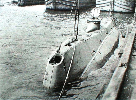
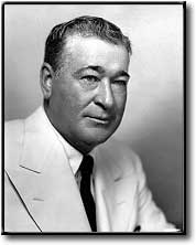
Designed in 1896 by Irish-American inventor John Phillip Holland and his Holland Torpedo Boat Company, the Holland VI was built at the Crescent Shipyard in Elizabeth, New Jersey, where Arthur Leopold Busch was the chief constructor / naval architect.  The Holland VI was launched on 17 May 1897. This diminutive submarine (by today’s standards) had an overall length of 53 ft 10 in (16.41 m), displacements of 65 tons surfaced / 75 tons submerged, and was operated by a crew of six.

Picture post card of the USS Holland (SS-1). 
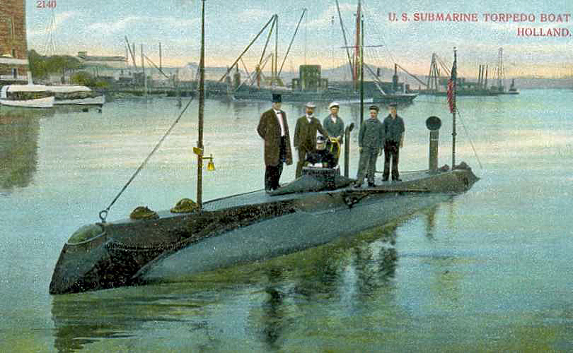
Source: Universal Ship Cancellation Society (USCS #3608)

The Holland VI brought together a host of impressive features for the first time in one vessel, including:

  • Efficient hydrodynamic hull shape [teardrop-shape with bulbous bow and tapered stern] with good seakeeping ability on the open ocean.
  • Separate main and auxiliary ballast systems enable rapid diving and surfacing with minimial changes to the longitudinal center of gravity while underway.
    • Accomplished by operating with full or nearly full ballast tanks when submerged.
    • Allowed precise control of trim angle while submerged.
  • Able to dive to and accurately maintain a significant depth [up of 75 feet (23 m)].
    • Diving planes provide the means to precisely control depth [stern planes only, located behind the propeller].
  • Dual propulsion systems driving a single propeller at the stern.
    • Internal combustion engine provides reliable power on the surface, enabling long transits while charging the batteries [up to 200 nautical miles (370 km) at 6 knots]
    • Lead-acid storage batteries provide power to run submerged for a considerable distance [about 30 nautical miles (56 km) at 5.5 knots].
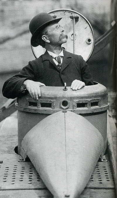
  • Conning tower for directing ship and weapons activities on the surface or semi-submerged.
    • No periscope. View ports around the top of the conning tower provided the commander with intermittent views while “porpoising” semi-submerged near the surface.
  • Offensive weapons systems.
    • One reloadable torpedo tube at the bow, with three self-propelled torpedoes carried internally.
    • One pneumatic dynamite gun at the bow that, on the surface, fired large projectiles, sometimes called “aerial torpedoes.” [This was subsequently removed].

John P. Holland first demonstrated the Holland VI to the U.S. Navy on 17 March 1898. It appears that Submarine Day originally was celebrated to mark anniversaries of this date.

USS Holland (SS-1) internal and external arrangements.  
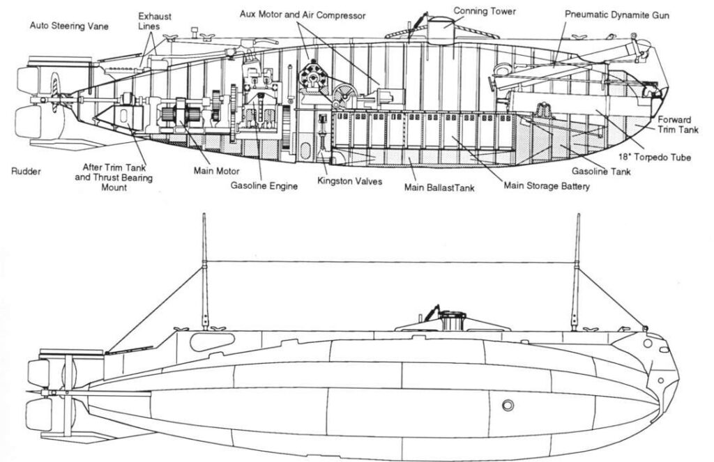
The interior space was one contiguous compartment. Source: Navsource.com

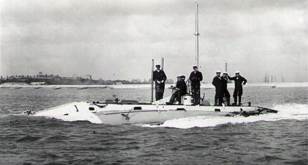
The U.S. Navy purchased the Holland VI for $150,000 on 11 April 1900. The Navy renamed and commissioned the submarine as the USS Holland on 12 October 1900. While the Navy previously owned and operated two submarines, Alligator (1862 – 63) and Intelligent Whale (1869 – 73), the USS Holland was the first commissioned submarine in the fleet. Lieutenant H.H. Caldwell became the first commanding officer of a modern commissioned submarine. 

On 25 August 1905, the USS Holland made history by being the first American submarine to carry a U.S. President, Theodore Roosevelt, while she ran submerged for 55 minutes.The Navy ordered six more Holland-class submarines from the Electric Boat Company, which was founded in 1899 and had acquired the Holland Torpedo Boat Company and the continuing services of John P. Holland as Manager. Patent US702729 was granted on 17 June 1902 for Holland’s submarine design and assigned to Electric Boat Company.

Bow quarter view of USS Holland (SS-1) in drydock.
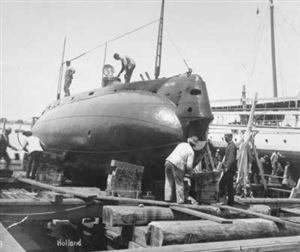
Source: Naval Institute photo archive
Stern quarter view of USS Holland (SS-1) in drydock. 
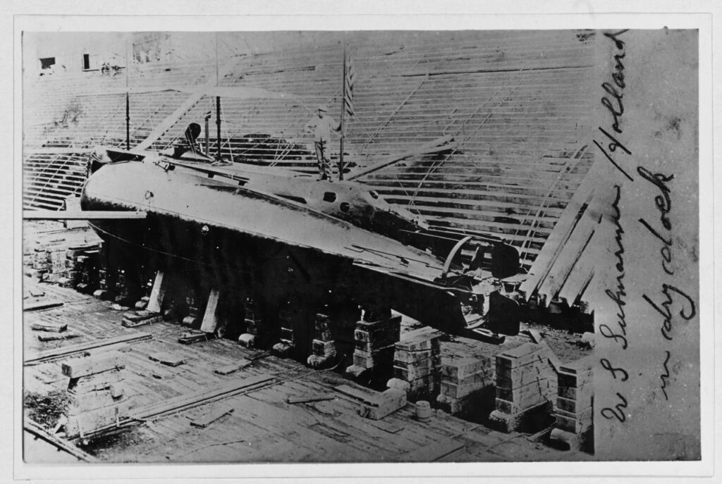
Source: Naval History and Heritage Command
Bow view of USS Holland (SS-1) dockside showing the muzzle of the 
pneumatic dynamite gun at the bow and the open conning tower amidships.  
Source: Scientific American 1898 via Wikimedia Commons
John Philip Holland in the conning tower. Note the viewing ports around the top rim of the tower. Source: Wikimedia Commons
Reenactment showing the interior of the conning tower.
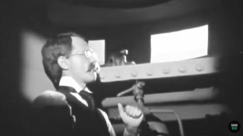
Source: screenshot from “Submarine #1” video (2022) 

The U.S. Navy’s Holland-class subs rapidly became obsolete as submarine technology advanced. USS Holland finished out her naval career in Norfolk, VA, was stricken from the Navy Register of Ships on 21 November 1910, and was sold for scrap in 1913. The USS Holland did not receive its “SS-1” designation until the Navy’s modern hull classification system was instituted on 17 July 1920.

3. The UK Holland-class submarines

In their online history, BAE Systems reports, “Following meetings with the Admiralty, an agreement was made on 27th October 1900 between the Electric Boat Company and Vickers Sons & Maxim Ltd of Barrow-in-Furness, giving Vickers 25-year license to manufacture the Holland-class of submarines, using Electric Boats patents.”

Vickers built five Holland-class subs for the Royal Navy. These were somewhat larger than their U.S. counterparts, with a length of 63 ft 4 in (19.3 m), a submerged displacement of 107 tons and a crew of eight.

HMS Holland 1 underway. Source: RN Submarine Museum via Wikipedia

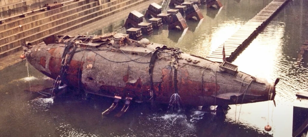
The first sub, designated Holland 1, was launched in 1901.  After 12 years of service, it was decommissioned in 1913 and sank at sea while under tow near Plymouth, on its way to be scrapped. The location of the sunken sub was discovered in 1981 and the largely intact vessel was raised in 1983. Today, the Holland 1 is on display at the Royal Navy’s Submarine Museum in Gosport, UK, in a climate-controlled environment designed to arrest further corrosion. 

UK’s Holland 1 in a drydock after being recovered from the seabed in 1983.
Source: screenshot from The National Museum of the Royal Navy video (2022)

The last of the UK’s Holland-class submarines, Holland 5, was launched in 1904. After eight years in service, Holland 5 sank off the coast of Sussex in 1912 while being towed for decommissioning. In 1985, the intact, but encrusted, submarine was located on the seabed at a depth of 35 meters (115 ft), where it remains today, subject to the Protection of Wrecks Act 1973.

Map of the UK’s HMS Holland 5 on the seabed.
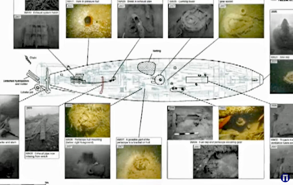
Source: screenshot from Wessex Archaeology video (2010)

4. The Japanese Holland-class submarines

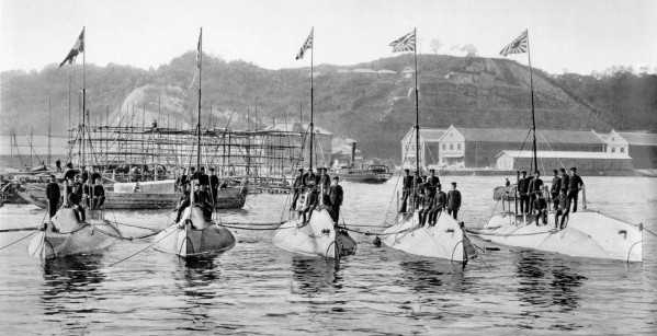
Japanese representatives had sailed aboard Holland IV during early testing in 1898 and during trials on the Potomac River in 1900. During the Russo-Japanese War, the Japanese government purchased five “improved” Holland-class submarines from the Electric Boat Company in great secrecy, since the U.S. was a “neutral” nation. These submarines had a length of 67 ft (20.4 m) and a submerged displacement of 126 tons. They were delivered to Japan partially assembled in December 1904. Assembly was completed at the Yokosuka Naval Arsenal, the crews were trained, and the submarines were ready for combat operations in August 1905. None saw action before the war ended in September 1905. They served as training boats until being retired from service 1920.

Japan’s first submarine squadron consisted of five “improved” Holland-class
(Type 7-P) subs. Source: Dynamic America, edited by J. Niven, 1960, 
via Gary McCue

5. Comparison with today’s nuclear-powered submarines

Since the first production run of Holland-class submarines built for the U.S. Navy, Electric Boat Company (now General Dynamics Electric Boat) has been delivering submarines to the Navy for more than 120 years.

The Navy’s Virginia-class SSNs, which started entering the fleet in 2004 with USS Virginia(SSN-774), are 7,800 ton behemoths in comparison to the USS Holland.

Comparison of USS Holland (SS-1) & USS Virginia (SSN-774)
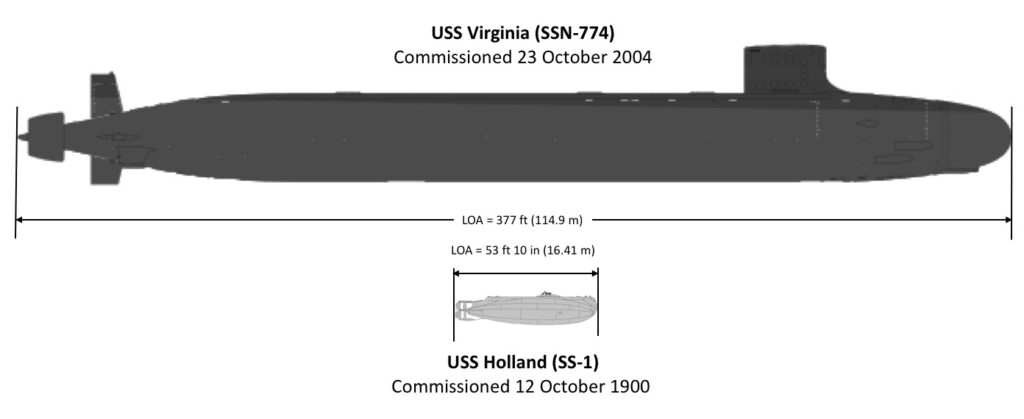
Sources: composite adapted from Wikiwand (SSN-774) & Navsource (SS-1)

Almost 20 years later, the latest Virginia-class Block V SSNs are even bigger, with an overall length of 460 ft (140 m) and a submerged displacement of over 10,000 tons. The largest submarines currently in the Navy’s fleet are the aging Ohio-class SSBNs (strategic missile submarines) and SSGNs (cruise missile submarines). With an overall length of 560 ft (170 m) and a submerged displacement of about 18,750 tons, the Ohio-class subs dwarf all the other U.S. subs.  

Since 2018, the U.S. Navy has been testing a large, autonomous, unmanned underwater vehicle (UUV), Echo Voyager, which is 51 feet (15.5 meters) long and has a displacement of about 50 tons. This is approximately the same size as the USS Holland (SS-1).

John P. Holland would be amazed at the progress made in submarine design and operation over the 123 years since the USS Holland was acquired by the U.S. Navy in 1990 and commissioned that same year.

Enjoy National Submarine Day on 11 April, and remember that, in the U.S., it’s pronounced “sub-marine-er,” not “sub-mariner,” as they say in the UK and in Marvel Comics.  If you’re going to dress up for the occasion, may I suggest this stylish T-shirt.

Source: Etsy

For more information

Patent

Videos – USS Holland

Videos – Royal Navy Holland-class submarines

U.S. Development of Lethal Autonomous Weapon Systems

Peter Lobner

Introduction

In November 2022, the Congressional Research Service (CRS) published an update to their document, “Defense Primer: U.S. Policy on Lethal Autonomous Weapon Systems,” which is available on the CRS website here: https://s3.documentcloud.org/documents/23310494/if11150.pdf

Each of the US military services has its own autonomous vehicle / weapons system programs.  Following is a brief roadmap to those programs.

Navy

In November 2022, CRS published an update to their document, “Navy Large Unmanned Surface and Undersea Vehicles: Background and Issues for Congress,” which you can read here: https://s3.documentcloud.org/documents/21271730/navy-large-unmanned-surface-and-undersea-vehicles-background-and-issues-for-congress-feb-17-2022.pdf

See my April 2016 post, “Large Autonomous Vessels will Revolutionize the U.S. Navy,” for background information on the Navy’s autonomous vessel program and the Sea Hunter prototype developed by Leidos and tested in San Diego: https://lynceans.org/tag/continuous-trail/

The Navy’s San Diego-based Unmanned Surface Vessel Division One is playing an important role in developing and testing several autonomous vessels.

Medium displacement unmanned surface vessels Seahawk (front) and Sea Hunter leave San Diego Bay ahead of the large manned destroyer USS Zumwalt.
Source: USNI 2021

For more information on the Navy’s autonomous vessel program, check out these US Naval Institute articles:

Air Force

In July 2022, CRS provided an overview of unmanned and autonomous aerial system in their report, “Unmanned Aircraft Systems: Roles, Missions, and Future Concepts,” which you’ll find here: https://crsreports.congress.gov/product/pdf/R/R47188

In one program, the USAF now is testing an AI-controlled F-16 fighter aircraft in aerial combat scenarios.  Here’s the February 2023 story: https://www.military.com/daily-news/2023/02/22/fully-autonomous-f-16-fighter-jet-takes-part-dogfights-during-tests.html?ESRC=eb_230223.nl

In another program, the USAF is developing an autonomous “wingman” aircraft to fly along with manned fighter aircraft to provide greater capabilities to attack a target and/or provide protection for the manned aircraft.  This development is described in a February 2022 article on The Drive website here: https://www.defensenews.com/air/2022/02/13/how-autonomous-wingmen-will-help-fighter-pilots-in-the-next-war/

Defense contractor Kratos, which has offices in San Diego, has important roles in several DoD autonomous aerial systems projects.

An XQ-58A Valkyrie unmanned aerial vehicle flies in formation with an F-22 Raptor and F-35A Lightning over the U.S. Army Yuma Proving Ground testing range, Ariz., during a series of tests in Dec. 2020. Source: USAF photo

Army

In January 2023, CRS published an update to their document, ”The Army’s Robotic Combat Vehicle (RCV) Program,” which is available here: https://crsreports.congress.gov/product/pdf/IF/IF11876

Army’s Robotic Combat Vehicle RCV-M (medium) prototype. Source: CRS

As you can see, there’s a lot going on in this field and capabilities for use of lethal autonomous systems may soon challenge limits set by present policy.

DoD’s Project Pele microreactor is being developed by BWXT with a target for initial operation at a DoD facility in 2027

Peter Lobner

In 2016 the Defense Science Board (DSB) identified energy as a critical enabler of future military operations. The DoD’s Strategic Capabilities Office (SCO) launched Project Pele with the objective to design, build, and demonstrate a prototype mobile nuclear reactor to provide reliable and resilient electric power, while minimizing risk of nuclear proliferation, environmental damage, or harm to nearby personnel or populations. 

The Pele reactor will be the first electricity-generating Generation IV nuclear reactor built in the United States. Check out the DoD Office of the Under Secretary of Defense, Research and Engineering (OUSD(R&E)) website for the Project Pele Environmental Impact Statement (EIS) here: https://www.cto.mil/pele_eis/

In June 2022, Department of Defense (DoD) selected BWXT to produce a single prototype Pele mobile microreactor, which will be a Brayton-cycle high-temperature gas-cooled reactor (HTGR) capable of generating an electrical output of 1 MWe to 5 MWe. See the story in Power magazine here: https://www.powermag.com/dod-picks-bwxt-to-manufacture-project-pele-prototype-nuclear-microreactor/

The Pele reactor will use High-Assay, Low-Enriched Uranium (HALEU, <20% enriched) fuel in the form of TRstructural ISOtropic (TRISO) coated fuel pellets (each about the size of a poppy seed). 

Cross-section of a TRISO particle, greatly magnified.
Source: DOE

The reactor will be assembled and initially operated at the Idaho National Laboratory (INL), under the safety oversight of the Department of Energy (DOE).  The Pele reactor is expected to be transportable by rail, truck or cargo aircraft.

Pele reactor modes of transportation. Source: GAO

There’s a good status update on Project Pele in a February 2023 article on the Energy Intelligence website, “Interview: Pentagon’s Jeff Waksman on Project Pele Microreactor,” at the following link: https://www.energyintel.com/00000186-7b02-d1cb-a3ee-ffbf32940000

For more information

Riding the Phantom Zephyr

Peter Lobner, updated 21 February 2021

1.  Background

When charged molecules in the air are subjected to an electric field, they are accelerated. When these charged molecules collide with neutral ones, they transfer part of their momentum, leading to air movement known as an “ionic wind.”  This basic process is shown in the following diagram, which depicts a strong electric field between a discharge electrode (left) and a ground electrode (right), and the motion of negative ions toward the ground electrode where they are collected.  The neutral molecules pass through the ground electrode and generate the thrust called the ionic wind.

This post summarizes work that has been done to develop ionic wind propulsion systems for aircraft.  The particular projects summarized are the following:

  • Major Alexander de Seversky’s Ionocraft vertical lifter (1964)
  • Michael Walden / LTAS lighter-than-air XEM-1 (1977)
  • Michael Walden / LTAS lighter-than-air EK-1 (2003)
  • The Festo b-IONIC Airfish airship (2005)
  • NASA ionic wind study (2009)
  • The MIT electroaerodynamic (EAD) heaver-than-air, fixed wing aircraft (2018)

In addition, we’ll take a look at recent ionic propulsion work being done by Electrofluidsystems Ltd., Electron Air LLC and the University of Florida’s Applied Physics Research Group.

2.  Scale model of ion-propelled Ionocraft vertical takeoff lifter flew in 1964

Major Alexander de Seversky developed the design concept for a novel aircraft concept called the “Ionocraft,” which was capable of hovering or moving in any direction at high altitudes by means of ionic discharge. His design for the Ionocraft is described in US Patent 3,130,945, “Ionocraft,” dated 28 April 1964.  You can read this patent here: https://patents.google.com/patent/US3130945A/en

The operating principle of de Seversky’s Ionocraft propulsion system is depicted in the following graphic.

Ion propulsion scheme implemented in the de Seversky Ionocraft. 
Source: Popular Mechanics, August 1964

In 1964, de Seversky built a two-ounce (57 gram) Ionocraft scale model and demonstrated its ability to fly while powered from an external 90 watt power conversion system (30,000 volts at 3 mA), significantly higher that conventional aircraft and helicopters.  This translated into a power-to-weight ratio of about 0.96 hp/pound.  You can watch a short 1964 video of a scale model Ionocraft test flight here: 

Screenshot showing Ionocraft scale model in flight
Screenshot showing ionic wind downdraft under an Ionocraft scale model in flight

De Seversky’s Ionocraft and its test program are described in an article in the August 1964 Popular Mechanics magazine, which is available at the following link:  https://books.google.com/books?id=ROMDAAAAMBAJ&printsec=frontcover&source=gbs_ge_summary_r&cad=0#v=onepage&q&f=false

Alexander de Seversky’s one-man Ionocraft concept.
Source: Popular Mechanics Archive, August 1964
Alexander de Seversky’s Ionocraft commuter concept.
Source: Popular Mechanics Archive, August 1964
1969 Soviet concepts for passenger carrying Ionocraft.
Technology for Youth magazine, 1969, Issue 7.

In the 1960s, engineers found that Ionocraft technology did not scale up well and they were unable to build a vehicle that could generate enough lift to carry the equipment needed to produce the electricity needed to drive it.

3.  The first free-flying, ion-propelled, lighter-than-air craft flew in 1977:  Michael Walden / LTAS XEM-1

The subscale XEM-1 proof-of-concept demonstrator was designed by Michael Walden and built in 1974 by his firm, Lighter Than Air Solar (LTAS) in Nevada.  After leaving LTAS in 2005, Michael Walden founded Walden Aerospace where he is the President and CTO, building on the creative legacy of his work with the former LTAS firms.  The Walden Aerospace website is here: http://walden-aerospace.com/HOME.html 

The basic configuration of this small airship is shown in the following photo.  The MK-1 ionic airflow (IAF) hybrid EK drives are mounted on the sides of the airship’s rigid hull.

Source: Walden Aerospace.
Basic configuration of the MK-1 ionic airflow (IAF)
hybrid EK drive. Source: Walden Aerospace.

XEM-1 originally was tethered by cable to an external control unit and later was modified for wireless remote control operation. In this latter configuration, XEM-1 demonstrated the use of a hybrid EK propulsion system in a self-powered, free-flying vehicle.  

Walden described the MK-1 IAF EK drive as follows:  “The duct included a 10 inch ‘bent tip’ 3-bladed prop running on an electric motor to create higher pressures through the duct, making it a ‘modified pressure lifter’…. The duct also had a circular wire emitter, a dielectric separator and a toroidal collector making it a ‘toroid lifter’.”

The later MK-2 and MK-3 IAF EK drives had a similar duct configuration.  In all of these EK drives, the flow of ions from emitter to collector imparts momentum to neutral air molecules, creating usable thrust for propulsion.  You’ll find more information on the MK-1 IAF EK drive and later versions on the Walden Aerospace website here:  http://walden-aerospace.com/Waldens_Patents_files/Walden%20Aerospace%20Advanced%20Technologies%2011092013-2.pdf

The XEM-1 was demonstrated to the Department of Defense (DoD) and Department of Energy (DOE) in 1977 at Nellis Air Force Base in Nevada.  Walden reported:  “We flew the first fully solar powered rigid airship in 1974, followed by a US Department of Defense and Department of Energy flight demonstration in August 1977”…. “ DoD was interested in this work to the extent that some of it is still classified despite requests for the information to become freely available.”

Walden credits the XEM-1 with being the first fully self-contained air vehicle to fly with a hybrid ionic airflow electro-kinetic propulsion system. This small airship also demonstrated the feasibility of a rigid, composite, monocoque aeroshell, which became a common feature on many later Walden / LTAS airships.

4.  The second free-flying, ion-propelled, lighter-than-air craft flew in 2003:  Michael Walden / LTAS EK-1

Michael Walden designed the next-generation EK-1, which was a remotely controlled, self-powered, subscale model of a lenticular airship with a skin-integrated EK drive that was part of the outer surface of the hull.  The drive was electronically steered to provide propulsion in any direction with no external aerodynamic surfaces and no moving parts.

EK-1 aloft in the hanger.  Source: LTAS / Walden Aerospace
EK-1 with a skin-integrated propulsion system moving during hanger test flight in 2003.Source: LTAS / Walden Aerospace
 

In June 2003, LTAS rented a hangar at the Boulder City, NV airport to build and fly the EK-1.  Testing the EK-1 was concluded in early August 2003 after demonstrating the technology to National Institute for Discovery Science (NIDS) board members.

Based on the EK-1 design, a full-scale EK airship would have a rigid, aeroshell comprised largely of LTAS MK-4 lithographic integrated thruster / structure hull panels.  As with other contemporary Walden / LTAS airship designs, the MK-4 panel airship likely would have implemented density controlled buoyancy (DCB) active aerostatic lift control and would have had a thin film solar array on the top of the aeroshell.

Artist’s concept of a MK-4 panel airship.
Source: Walden Aerospace

5.  The third free-flying, ion-propelled, lighter-than-air craft flew in 2005: the Festo b-IONIC Airfish

The Festo b-IONIC Airfish airship was developed at the Technical University of Berlinwith guidance of the firm Festo AG & Co. KG.  This small, non-rigid airship is notable because, in 2005, it became the first aircraft to fly with a solid state propulsion system.  The neutrally-buoyant Airfish only flew indoors, in a controlled environment, at a very slow speed, but it flew.

Airfish. Source:  Festo AG & Co. KG

Some of the technical characteristics of the Airfish are listed below:

  • Length:  7.5 meters (24.6 ft)
  • Span: 3.0 meters (9.8 ft)
  • Shell diameter: 1.83 meters (6 ft)
  • Helium volume:  9.0 m3(318 ft3)
  • Total weight:  9.04 kg (19.9 lb)
  • Power source in tail: 12 x 1,500 mAh lithium-ion polymer cells (18 Ah total)
  • Power source per wing (two wings): 9 x 3,200 mAh lithium-ion polymer cells (28.8 Ah total)
  • High voltage: 20,000 to 30,000 volts
  • Buoyancy:  9.0 – 9.3 kg (19.8 – 20.5 lb)
  • Total thrust:  8 – 10 grams (0.018 – 0.022 pounds) 
  • Maximum velocity: 0.7 meters/sec (2.5 kph; 1.6 mph)

The b-IONIC Airfish employed two solid state propulsion systems, an electrostatic ionic jet and a plasma ray, which Festo describes as follows:

  • Electrostatic ionic jet:  “At the tail end Airfish uses the classic principle of an electrostatic ionic jet propulsion engine. High-voltage DC-fields (20-30 kV) along thin copper wires tear electrons away from air molecules. The positive ions thus created are then accelerated towards the negatively charged counter electrodes (ring-shaped aluminum foils) at high speeds (300-400 m/s), pulling along additional neutral air molecules. This creates an effective ion stream with speeds of up to 10 m/s.”
  • Plasma-ray:  “The side wings of Airfish are equipped with a new bionic plasma-ray propulsion system, which mimics the wing based stroke principle used by birds, such as penguins, without actually applying movable mechanical parts. As is the case with the natural role model, the plasma-ray system accelerates air in a wavelike pattern while it is moving across the wings.”
Airfish.  Source: Festo AG & Co. KG
Airfish.  Source: Festo AG & Co

The Festo b-IONIC Airfish demonstrated that a solid state propulsion system was possible.  The tests also demonstrated that the solid state propulsion systems also reduced drag, raising the intriguing possibility that it may be possible to significantly reduce drag if an entire vessel could be enclosed in a ionized plasma bubble.You’ll find more information on the Festo b-IONIC Airfish, its solid state propulsion system and implications for drag reduction in the the Festo brochure here: https://www.festo.com/net/SupportPortal/Files/344798/b_IONIC_Airfish_en.pdf

You can watch a 2005 short video on the Festo b-IONIC Airfish flight here:

6.  NASA ionic wind study – 2009

A corona discharge device generates an ionic wind, and thrust, when a high voltage corona discharge is struck between sharply pointed electrodes and larger radius ground electrodes.

In 2009, National Aeronautics & Space Administration (NASA) researchers Jack Wilson, Hugh Perkins and William Thompson conducted a study to examine whether the thrust of corona discharge systems could be scaled to values of interest for aircraft propulsion.  Their results are reported in report NASA/TM-2009-215822, which you’ll find at the following link: https://ntrs.nasa.gov/archive/nasa/casi.ntrs.nasa.gov/20100000021.pdf

Key points of the study included:

  • Different types of high voltage electrodes were tried, including wires, knife-edges, and arrays of pins. A pin array was found to be optimum. 
  • Parametric experiments, and theory, showed that the thrust per unit power could be raised from early values of 5 N/kW to values approaching 50 N/kW, but only by lowering the thrust produced, and raising the voltage applied. 
  • In addition to using DC voltage, pulsed excitation, with and without a DC bias, was examined. The results were inconclusive as to whether this was advantageous. 
  • It was concluded that the use of a corona discharge for aircraft propulsion did not seem very practical.”

7.  The first heavier-than-air, fixed-wing, ion-propelled aircraft flew in 2018

On 21 November 2018, MIT researchers reported successfully flying the world’s first heavier-than-air, fixed-wing, ion-propelled (electroaerodynamic, EAD) aircraft.  You can read the paper by Haofeng Xu, et al., “Flight of an aeroplane with solid-state propulsion,” on the Nature website here: https://www.nature.com/articles/s41586-018-0707-9

The design of the MIT EAD aircraft is shown below:

a, Computer-generated rendering of the EAD airplane. 
b, Photograph of actual EAD airplane (after multiple flight trials).

Some of the technical characteristics of this MIT aircraft are listed below:

  • Wingspan: 4.9 meters (16 ft)
  • Total weight: 2.45 kg (5.4 lb)
  • Power source: powered by 54 x 3.7 volt 150 mAh lithium-ion polymer cells (8.1 Ah total)
  • High voltage: 40,000 volts (+ 20,000 volts / – 20,000 volts)
  • Total thrust: 3.2 N, 326 grams (0.718 pounds) 
  • Maximum velocity: 4.8 meters/sec (17.3 kph; 10.7 mph)

In their paper, the MIT researchers reported:

  • “We performed ten flights with the full-scale experimental aircraft at the MIT Johnson Indoor Track…. Owing to the limited length of the indoor space (60 m), we used a bungeed launch system to accelerate the aircraft from stationary to a steady flight velocity of 5 meters/sec within 5 meters, and performed free flight in the remaining 55 meters of flight space. We also performed ten unpowered glides with the thrusters turned off, in which the airplane flew for less than 10 meters. We used cameras and a computer vision algorithm to track the aircraft position and determine the flight trajectory.”
  • “All flights gained height over the 8–9 second segment of steady flight, which covered a distance of 40–45 meters…. The average physical height gain of all flights was 0.47 meters…. However, for some of the flights, the aircraft velocity decreased during the flight. An adjustment for this loss of kinetic energy…. results in an energy equivalent height gain, which is the height gain that would have been achieved had the velocity remained constant. This was positive for seven of the ten flights, showing that better than steady-level flight had been achieved in those cases.”
  • “In this proof of concept for this method of propulsion, the realized thrust-to-power ratio was 5 N/kW1, which is of the order of conventional airplane propulsion methods such as the jet engine.”  Overall efficiency was estimated to be 2.56%.

The propulsion principles of the MIT EAD aircraft are explained in relation to the following diagram in the November 2018 article by Franck Plouraboué, “Flying With Ionic Wind,” which you can read on the Nature website at the following link:  https://www.nature.com/articles/d41586-018-07411-z

The following diagram and explanatory text are reproduced from that article.

  • In Figure a, above: …an electric field (not shown) is applied to the region surrounding a fine wire called the emitter (shown in cross-section). The field induces electron cascades, whereby free electrons collide with air molecules (not shown in the cascades) and consequently free up more electrons. This process produces charged air molecules in the vicinity of the emitter — a corona discharge. Depending on the electric field, negatively or positively charged molecules drift away (red arrows) from the emitter. These molecules collide with neutral air molecules, generating an ionic wind (black arrows). 
  • In Figure b, above: The aircraft uses a series of emitters and devices called collectors, the longitudinal directions of which are perpendicular to the ionic wind. The flow of charged air molecules occurs mainly along the directions (red arrows) joining emitters and collectors. Consequently, the ionic wind is accelerated (black arrows) predominantly in these regions. 

You can view a short video of the MIT EAD aircraft test flights here:  

8.  The future of ionic propulsion for aerospace applications.

If it can be successfully developed to much larger scales, ionic propulsion offers the potential for aircraft to fly in the atmosphere on a variety of practical missions using only ionized air for propulsion.  Using other ionized fluid media, ionic propulsion could develop into a means to fly directly from the surface of the earth into the vacuum of space and then operate in that environment. The following organizations have been developing such systems.

Electrofluidsystems Ltd.

In 2006, the Technical University of Berlin’s Airfish project manager, Berkant Göksel, founded the firm Electrofluidsystems Ltd., which in 2012 was rebranded as IB Göksel Electrofluidsystems.  This firm presently is developing a new third generation of plasma-driven airships with highly reduced ozone and nitrogen oxide (NOx) emissions, magneto-plasma actuators for plasma flow control, and the company’s own blended wing type flying wing products.  You’ll find their website here:  https://www.electrofluidsystems.com

Source: Electrofluidsystems TU Berlin
Advanced plasma-driven aircraft concept. Source:  Electrofluidsystems TU Berlin

MIT researchers are developing designs for high-performance aircraft using ionic propulsion.  Theoretically, efficiency improves with speed, with an efficiency of 50% possible at a speed of about 1,000 kph (621 mph).  You can watch a short video on MIT work to develop a Star Trek-like ion drive aircraft here:  

Electron Air LLC

Another firm active in the field of ionic propulsion is Electron Air LLC (https://electronairllc.org), which, on 6 November 2018, was granted patent US10119527B2 for their design for a self-contained ion powered craft.  Their grid shaped craft is described as follows:

“The aircraft assembly includes a collector assembly, an emitter assembly, and a control circuit operatively connected to at least the emitter and collector assemblies and comprising a power supply configured to provide voltage to the emitter and collector assemblies. The assembly is configured, such that, when the voltage is provided from an on board power supply, the aircraft provides sufficient thrust to lift each of the collector assembly, the emitter assembly, and the entire power supply against gravity.”

The device, as shown in patent Figure 3, consists of a two-layer grid structure with a collector assembly (50), an emitter assembly (70) and peripheral supports (33 to 37).

You can read patent US10119527B2 here: https://patents.google.com/patent/US10119527B2/en?oq=10119527

This patent cites Alexander de Seversky’s Patent 3130945, “Ionocraft.”

You can watch a short (1:22 minute) video of an outdoor tethered test flight of a remotely controlled, self-contained, ion powered, heavier-than-air craft with onboard power at the following link: https://www.youtube.com/watch?v=aX21HCHlgKo

University of Florida, Applied Physics Research Group

In the early 2000s, a Wingless Electromagnetic Air Vehicle (WEAV) was invented by Dr. Subrata Roy, a plasma physicist and aerospace engineering professor at the University of Florida. WEAV is described as a heavier-than-air flight system that can self-lift, hover, and fly using plasma propulsion with no moving components. The laboratory-scale device is six inch (15.2 cm) in diameter.  The basic configuration of the disc-shaped craft is shown in patent 8960595B2 Figure 1.

This research project has been supported by the US Air Force Office of Scientific Research. You’ll find details on WEAV technology in the University of Florida’s 2011 final report at the following (very slow loading) link: https://apps.dtic.mil/dtic/tr/fulltext/u2/a564120.pdf

In this report, the authors describe the technology: “This revolutionary concept is based on the use of an electro-(or magneto) hydrodynamic (EHD/MHD) thrust generation surface that is coated with multiple layers of dielectric polymers with exposed and/or embedded electrodes for propulsion and dynamic control. This technology has the unique capability of imparting an accurate amount of thrust into the surrounding fluid enabling the vehicle to move and react. Thrust is instantaneously and accurately controlled by the applied power, its waveform, duty cycle, phase lag and other electrical parameters. Once the applied power is removed the thrust vanishes.”

The following patents related to WEAV technology have been filed and assigned to the University of Florida Research Foundation Inc.:

These patents do not cite Alexander de Seversky’s Patent 3130945, “Ionocraft.”

9.  More reading on electrodynamic propulsion for aircraft

General

MIT electroaerodynamic aircraft

Ionocraft lifters

WEAV

Declassified Military Satellite Imagery has Applications in a Wide Variety of Civilian Geospatial Studies

Peter Lobner, updated 26 October 2023

1. Overview of US military optical reconnaissance satellite programs

The National Reconnaissance Office (NRO) is responsible for developing and operating space reconnaissance systems and conducting intelligence-related activities for US national security.  NRO developed several generations of classified Keyhole (KH) military optical reconnaissance satellites that have been the primary sources of Earth imagery for the US Department of Defense (DoD) and intelligence agencies.  NRO’s website is here:

https://www.nro.gov

NRO’s early generations of Keyhole satellites were placed in low Earth orbits, acquired the desired photographic images on film during relatively short-duration missions, and then returned the film to Earth in small reentry capsules for airborne recovery. After recovery, the film was processed and analyzed.  The first US military optical reconnaissance satellite program, code named CORONA, pioneered the development and refinement of the technologies, equipment and systems needed to deploy an operational orbital optical reconnaissance capability. The first successful CORONA film recovery occurred on 19 August 1960.

Specially modified US Air Force C-119J aircraft recovers a
CORONA film canister in flight.  Source: US Air Force
First reconnaissance picture taken in orbit and successfully recovered on Earth;  taken on 18 August 1960 by a CORONA KH-1 satellite dubbed Discoverer 14.  Image shows the Mys Shmidta airfield in the Chukotka region of the Russian Arctic, with a resolution of about 40 feet (12.2 meters).  Source: Wikipedia

Keyhole satellites are identified by a code word and a “KH” designator, as summarized in the following table.

In 1976, NRO deployed its first electronic imaging optical reconnaissance satellite known as KENNEN KH-11 (renamed CRYSTAL in 1982), which eventually replaced the KH-9, and brought an end to reconnaissance satellite missions requiring film return.  The KH-11 flies long-duration missions and returns its digital images in near real time to ground stations for processing and analysis.  The KH-11, or an advanced version sometimes referred to as the KH-12, is operational today.

US film-return reconnaissance satellites from KH-1 to KH-9 shown to scale
with the KH-11 electronic imaging reconaissance satellite.  
Credit: Giuseppe De Chiara and The Space Review.

Geospatial intelligence, or GEOINT, is the exploitation and analysis of imagery and geospatial information to describe, assess and visually depict physical features and geographically referenced activities on the Earth. GEOINT consists of imagery, imagery intelligence and geospatial information.  Satellite imagery from Keyhole reconnaissance satellites is an important information source for national security-related GEOINT activities.

The National Geospatial-Intelligence Agency (NGA), which was formed in 2003, has the primary mission of collecting, analyzing, and distributing GEOINT in support of national security.  NGA’s predecessor agencies, with comparable missions, were:

  • National Imagery and Mapping Agency (NIMA), 1996 – 2003
  • National Photographic Interpretation Center (NPIC), a joint project of the Central Intelligence Agency (CIA) and DoD, 1961 – 1996

The NGA’s web homepage, at the following link: https://www.nga.mil/Pages/Default.aspx

The NGA’s webpage for declassified satellite imagery is here: https://www.nga.mil/ProductsServices/Pages/Imagery.aspx

2. The advent of the US civilian Earth observation programs

Collecting Earth imagery from orbit became an operational US military capability more than a decade before the start of the joint National Aeronautics & Space Administration (NASA) / US Geological Survey (USGS) civilian Landsat Earth observation program.  The first Landsat satellite was launched on 23 July 1972 with two electronic observing systems, both of which had a spatial resolution of about 80 meters (262 feet). 

Since 1972, Landsat satellites have continuously acquired low-to-moderate resolution digital images of the Earth’s land surface, providing long-term data about the status of natural resources and the environment. Resolution of the current generation multi-spectral scanner on Landsat 9 is 30 meters (98 feet) in visible light bands. 

You’ll find more information on the Landsat program on the USGS website here: https://www.usgs.gov/land-resources/nli/landsat

3. Declassification of certain military reconnaissance satellite imagery

All military reconnaissance satellite imagery was highly classified until 1995, when some imagery from early defense reconnaissance satellite programs was declassified.  The USGS explains:

“The images were originally used for reconnaissance and to produce maps for U.S. intelligence agencies. In 1992, an Environmental Task Force evaluated the application of early satellite data for environmental studies. Since the CORONA, ARGON, and LANYARD data were no longer critical to national security and could be of historical value for global change research, the images were declassified by Executive Order 12951 in 1995”

You can read Executive Order 12951 here: https://www.govinfo.gov/content/pkg/WCPD-1995-02-27/pdf/WCPD-1995-02-27-Pg304.pdf

Additional sets of military reconnaissance satellite imagery were declassified in 2002 and 2011 based on extensions of Executive Order 12951.

The declassified imagery is held by the following two organizations:

  • The original film is held by the National Archives and Records Administration (NARA).
  • Duplicate film held in the USGS Earth Resources Observation and Science (EROS) Center archive is used to produce digital copies of the imagery for distribution to users.

The declassified military satellite imagery available in the EROS archive is summarized below:

USGS EROS Archive – Declassified Satellite Imagery – 1 (1960 to 1972)

  • This set of photos, declassified in 1995, consists of more than 860,000 images of the Earth’s surface from the CORONA, ARGON, and LANYARD satellite systems.
  • CORONA image resolution improved from 40 feet (12.2 meters) for the KH-1 to about 6 feet (1.8 meters) for the KH-4B.
  • KH-5 ARGON image resolution was about 460 feet (140 meters).
  • KH-6 LANYARD  image resolution was about 6 feet (1.8 meters).

USGS EROS Archive – Declassified Satellite Imagery – 2 (1963 to 1980)

  • This set of photos, declassified in 2002, consists of photographs from the KH-7 GAMBIT surveillance system and KH-9 HEXAGON mapping program.
  • KH-7 image resolution is 2 to 4 feet (0.6 to 1.2 meters).  About 18,000 black-and-white images and 230 color images are available.
  • The KH-9 mapping camera was designed to support mapping requirements and exact positioning of geographical points. Not all KH-9 satellite missions included a mapping camera.  Image resolution is 20 to 30 feet (6 to 9 meters); significantly better than the 98 feet (30 meter) resolution of LANDSAT imagery.  About 29,000 mapping images are available.

USGS EROS Archive – Declassified Satellite Imagery – 3 (1971 to 1984)

  • This set of photos, declassified in 2011, consists of more photographs from the KH-9 HEXAGON mapping program.  Image resolution is 20 to 30 feet (6 to 9 meters).

More information on the declassified imagery resources is available from the USGS EROS Archive – Products Overview webpage at the following link (see heading “Declassified Data”): https://www.usgs.gov/centers/eros/science/usgs-eros-archive-products-overview?qt-science_center_objects=0#qt-science_center_objects

4.  Example applications of declassified military reconnaissance satellite imagery

The declassified military reconnaissance satellite imagery provides views of the Earth starting in the early 1960s, more than a decade before civilian Earth observation satellites became operational.  The military reconnaissance satellite imagery, except from ARGON KH-5, is higher resolution than is available today from Landsat civilian earth observation satellites. The declassified imagery is an important supplement to other Earth imagery sources.  Several examples applications of the declassified imagery are described below.

4.1 Assessing Aral Sea depletion

USGS reports: “The Aral Sea once covered about 68,000 square kilometers, a little bigger than the U.S. state of West Virginia. It was the 4th largest lake in the world. It is now only about 10% of the size it was in 1960…..In the 1990s, a dam was built to prevent North Aral water from flowing into the South Aral. It was rebuilt in 2005 and named the Kok-Aral Dam…..The North Aral has stabilized but the South Aral has continued to shrink and become saltier. Up until the 1960s, Aral Sea salinity was around 10 grams per liter, less than one-third the salinity of the ocean. The salinity level now exceeds 100 grams per liter in the South Aral, which is about three times saltier than the ocean.”

On the USGS website, the “Earthshots: Satellite Images of Environmental Change” webpages show the visible changes at many locations on Earth over a 50+ year time period.  The table of contents to the Earthshots webpages is shown below and is at the following link: http:// https://earthshots.usgs.gov/earthshots/

USGS Earthshots Table of Contents

For the Aral Sea region, the Earthshots photo sequences start with ARGON KH-5 photos taken in 1964.  Below are three screenshots  of the USGS Earthshots pages showing the KH-5 images for the whole the Aral Sea, the North Aral Sea region and the South Aral Sea region. You can explore the Aral Sea Earthshots photo sequences at the following link: https://earthshots.usgs.gov/earthshots/node/91#ad-image-0-0

4.2 Assessing Antarctic ice shelf condition

In a 7 June 2016 article entitled, ”Spy satellites reveal early start to Antarctic ice shelf collapse,” Thomas Sumner reported:

“Analyzing declassified images from spy satellites, researchers discovered that the downhill flow of ice on Antarctica’s Larsen B ice shelf was already accelerating as early as the 1960s and ’70s. By the late 1980s, the average ice velocity at the front of the shelf was around 20 percent faster than in the preceding decades,….”

You can read the complete article on the ScienceNews website here: https://www.sciencenews.org/article/spy-satellites-reveal-early-start-antarctic-ice-shelf-collapse

Satellite images taken by the ARGON KH-5 satellite have revealed how the accelerated movement that triggered the collapse of the Larsen B ice shelf on the east side of the Antarctic Peninsula began in the 1960s. The declassified images taken by the satellite on 29 August 1963 and 1 September 1963 are pictured right.  
Source: Daily Mail, 10 June 2016

4.3 Assessing Himalayan glacier condition

In a 19 June 2019 paper “Acceleration of ice loss across the Himalayas over the past 40 years,” the authors, reported on the use of HEXAGON KH-9 mapping camera imagery to improve their understanding of trends affecting the Himalayan glaciers from 1975 to 2016:

“Himalayan glaciers supply meltwater to densely populated catchments in South Asia, and regional observations of glacier change over multiple decades are needed to understand climate drivers and assess resulting impacts on glacier-fed rivers. Here, we quantify changes in ice thickness during the intervals 1975–2000 and 2000–2016 across the Himalayas, using a set of digital elevation models derived from cold war–era spy satellite film and modern stereo satellite imagery.”

“The majority of the KH-9 images here were acquired within a 3-year interval (1973–1976), and we processed a total of 42 images to provide sufficient spatial coverage.”

“We observe consistent ice loss along the entire 2000-km transect for both intervals and find a doubling of the average loss rate during 2000–2016.”

“Our compilation includes glaciers comprising approximately 34% of the total glacierized area in the region, which represents roughly 55% of the total ice volume based on recent ice thickness estimates.”

You can read the complete paper by J. M. Maurer, et al., on the Science Advances website here: https://advances.sciencemag.org/content/5/6/eaav7266

3-D image of the Himalayas derived from HEXAGON KH-9 satellite mapping photographs taken on December 20, 1975. Source:  J. M. Maurer/LDEO

4.4 Discovering archaeological sites

A. CORONA Atlas Project

The Center for Advanced Spatial Technologies, a University of Arkansas / U.S. Geological Survey collaboration, has undertaken the CORONA Atlas Project using military reconnaissance satellite imagery to create the “CORONA Atlas & Referencing System”. The current Atlas focuses on the Middle East and a small area of Peru, and is derived from 1,024 CORONA images taken on 50 missions. The Atlas contains 833 archaeological sites.

“In regions like the Middle East, CORONA imagery is particularly important for archaeology because urban development, agricultural intensification, and reservoir construction over the past several decades have obscured or destroyed countless archaeological sites and other ancient features such as roads and canals. These sites are often clearly visible on CORONA imagery, enabling researchers to map sites that have been lost and to discover many that have never before been documented. However, the unique imaging geometry of the CORONA satellite cameras, which produced long, narrow film strips, makes correcting spatial distortions in the images very challenging and has therefore limited their use by researchers.”

Screenshot of the CORONA Atlas showing regions in the Middle East
with data available.

CAST reports that they have “developed methods for efficient 

orthorectification of CORONA imagery and now provides free public access to our imagery database for non-commercial use. Images can be viewed online and full resolution images can be downloaded in NITF format.”  

The can explore the CORONA Atlas & Referencing System here: https://corona.cast.uark.edu

B. Dartmouth “Fertile Crescent” Study

In October 2023, a team from Dartmouth College published a paper that described their recent discovery of 396 Roman-era forts using declassified CORONA and HEXAGON spy satellite imagery of regions of Syria, Iraq and nearby “fertile crescent” territories of the eastern Mediterranean. The study area is shown in the following map. A previous aerial survey of the area in 1934 had identified 116 other forts in the same region.

Dartmouth study area. Source: J. Casana, et al. (26 October 2023)

The authors noted, “Perhaps the most significant realization from our work concerns the spatial distribution of the forts across the landscape, as this has major implications for our understanding of their intended purpose as well as for the administration of the eastern Roman frontier more generally.”

Comparison of the distribution of forts documented in the 1934 aerial survey (top)and forts found recently on declassified satellite imagery (bottom). Source: Figure 9, J. Casana, et al. (26 October 2023)

Examples of the new forts identified by the Dartmouth team in satellite imagery are shown in the following figures.

CORONA images showing three major sites: (A) Sura (NASA1401); (B) Resafa (NASA1398); and (C) Ain Sinu (CRN999). Source: Figure 3, J. Casana, et al. (26 October 2023)

Castellum at Tell Brak site in multiple images: (A) CORONA (1102, 17 December 1967); (B) CORONA (1105, 4 November 1968); (C) HEXAGON (1204, 17 November 1974); and (D) modern satellite imagery. Source: Figure 4, J. Casana, et al. (26 October 2023)

The teams paper concludes: “Finally, the discovery of such a large number of previously undocumented ancient forts in this well-studied region of the Near East is a testament to the power of remote-sensing technologies as transformative tools in contemporary archaeological research.”

4.5 Conducting commercial geospatial analytics over a broader period of time

The firm Orbital Insight, founded in 2013, is an example of commercial firms that are mining geospatial data and developing valuable information products for a wide range of customers. Orbital Insight reports:

“Orbital Insight turns millions of images into a big-picture understanding of Earth. Not only does this create unprecedented transparency, but it also empowers business and policy decision makers with new insights and unbiased knowledge of socio-economic trends. As the number of Earth-observing devices grows and their data output expands, Orbital Insight’s geospatial analytics platform finds observational truth in an interconnected world. We map out and quantify the world’s complexities so that organizations can make more informed decisions.”

“By applying artificial intelligence to satellite, UAV, and other geospatial data sources, we seek to discover and quantify societal and economic trends on Earth that are indistinguishable to the human eye. Combining this information with terrestrial data, such as mobile and location-based data, unlocks new sources of intelligence.”

The Orbital Insight website is here: https://orbitalinsight.com/company/

5. Additional reading related to US optical reconnaissance satellites

You’ll find more information on the NRO’s film-return, optical reconnaissance satellites (KH-1 to KH-9) at the following links:

  • Robert Perry, “A History of Satellite Reconnaissance,” Volumes I to V, National Reconnaissance Office (NRO), various dates 1973 – 1974; released under FOIA and available for download on the NASA Spaceflight.com website, here: https://forum.nasaspaceflight.com/index.php?topic=20232.0

You’ll find details on NRO’s electronic optical reconnaissance satellites (KH-11, KH-12) at the following links:

6. Additional reading related to civilian use of declassified spy satellite imagery

General:

Assessing Aral Sea depletion:

Assessing Antarctic ice sheet condition:

Assessing Himalayan glacier condition:

Discovering archaeological sites:

Higgins Landing Craft had a Major Impact on the Outcome of World War II

Peter Lobner

Higgins landing craft are the ubiquitous, flat-bottomed, shallow-draft, barge-like boats used widely throughout WW II to deliver troops, vehicles and supplies from offshore ship to the beach during opposed (the enemy was shooting back) amphibious landings.  Designed by Andrew Jackson Higgins, these boats were built in large quantities at the Higgins Industries shipyard in New Orleans, LA, using a diverse labor force. 

The Higgins Memorial Project provides a biography of A. J. Higgins at the following link:

http://www.higginsmemorial.com/higgins.asp

The biographer notes: “In 1964, Dwight D. Eisenhower called Andrew Jackson Higgins ‘the man who won the war for us’.  Without Higgins’ famous landing crafts (LCPs, LCPLs, LCVPs, LCMs), the strategy of World War II would have been much different and winning the war much more difficult.”

Andrew Jackson Higgins
Source: Higgins Memorial Project

Higgins designed more than 60 types of landing craft, all built largely of mahogany plywood (same as the Higgins and other WW II PT boats), with a strong, internal wooden frame structure, and limited use of steel.  By the end of WW II, Higgins Industries has built more than 20,000 boats; 12,500 of them were LCVPs.

The first Higgins boats be used were the LCPs (Landing Craft, Personnel) and LCP(L)s (Landing Craft, Personnel, Large), which did not have a bow loading ramp. Men had to jump over the gunwales after the boat landed on the beach.

Higgins LCP(L).  Source: Wikipedia

Higgins LCVPs (Landing Craft, Vehicle, Personnel) were the primary way that soldiers, sailors, Marines and supplies got to the beaches of Normandy on D-Day.  The LCVPs has a steel bow loading ramp and steel armor plate added on the exterior of the hull.  They could ferry a platoon-sized complement of 36 soldiers with their equipment to shore at 9 knots (17 kph).  LCMs (Landing Craft, Mechanized) carried larger vehicles, including tanks, to shore. 

Source:  https://cs.stanford.edu/people/eroberts/courses/ww2/projects/fighting-vehicles/higgins-boat.htm
LCVP, circa April 1945.  Source: U.S. Navy photo

At the following link, you can read a 3 June 2019 article by David Kindy, “The Invention That Won World War II – Patented in 1944, the Higgins boat gave the Allies the advantage in amphibious assaults.” 

https://www.smithsonianmag.com/innovation/invention-won-world-war-ii-180972327/

That article notes one of the few surviving LCVPs is now on display outside of the U.S. Patent and Trademark Office headquarters and National Inventors Hall of Fame Museum in Alexandria, Virginia.

A surviving LCVP on display in Alexandria, VA. 
Source:  https://www.smithsonianmag.com/

A replica of a Higgins LCVP is at the National WW II Museum in New Orleans.

You can watch a 10-minute YouTube video history of the Higgins boats here:

https://www.youtube.com/watch?v=R7mW_0YwE84

The men who rode into combat during WW II in these little vessels were very brave men.  We owe them a debt of gratitude for their costly success in storming the beaches of Normandy 75 years ago and turning the tide of WW II.

JASON and NRAC Contracts Were Cancelled by the Pentagon in Early 2019 – JASON Has Survived but NRAC Has Not

Peter Lobner, updated 28 Jun 2019, 14 Dec 2019 & 12 May 2020

JASON and the Naval Research Advisory Committee (NRAC) are both established, independent advisory groups that have long histories of providing important scientific and technical advice to the U.S. government, primarily to Department of Defense (DoD) clients.  The Pentagon cancelled the JASON and NRAC contracts in early 2019.   Immediately, efforts were undertaken on several fronts to attempt to restore funding.   The efforts on behalf of JASON were successful, but NRAC was not so fortunate.

Following is an overview of these two advisory groups and an update on their current status.

1.  JASON

JASON is an independent advisory panel of elite scientists that was created in 1960 to address a wide range of scientific and technical issues, primarily for the U.S. military. Originally, the JASON panel had about 20 members, known informally as Jasons, increasing to about 40 members by the 1970s.  JASON maintains its independence by requiring that new members be selected by its existing members rather than by external sponsors.  

JASON is a very controversial organization with a very low public profile.  For a good introduction to JASON, I recommend Ann Finkbeiner’s 2006 book, “The Jasons: The Secret History of Science’s Postwar Elite,”  which is available from Amazon and other booksellers. You can watch an hour-long video created by Microsoft Research with Ann Finkbeiner providing an excellent narrative overview (no Powerpoint slides) on JASON here:

https://www.youtube.com/watch?v=FV1TBiwdZeg

Ann Finkbeiner notes: “Working in secrecy to solve highly classified problems for the Department of Defense, CIA, and NSA is an elite group of scientific advisors who provide the government with analyses on defense and arms control and they call themselves JASON.  Named for the hero in Jason and the Argonauts, the group grew out of the Manhattan Project and counts as its members scientists such as Freeman Dyson and Murray Gell-Mann.  Of the roughly one hundred Jasons over time, 43 have been elected to the National Academy of Sciences, eight have won MacArthur awards, one a Field’s Medal, and 11 have won Nobel Prizes.  Its members have gathered every summer since 1960, working in absolute secrecy and with unparalleled freedom.  The Jasons’ work poses vital questions: what role should the government play in scientific research? At what point is the inventor accountable for the hazards of the invention?”

You’ll find a list of JASON research topics compiled on Wikipedia here:

https://ipfs.io/ipfs/QmXoypizjW3WknFiJnKLwHCnL72vedxjQkDDP1mXWo6uco/wiki/JASON_(advisory_group).html

Most of the resulting JASON reports are classified.  You’ll find a list of unclassified JASON reports (and links) on the Federation of American Scientists (FAS) website at the following link: https://fas.org/irp/agency/dod/jason/

Since the late 1970s, the JASONs have been assigned tasks and been funded via Indefinite Delivery / Indefinite Quantity (IDIQ) contracts managed by MITRE Corporation.  The Office of the Secretary of Defense (OSD) issued MITRE’s most recent five-year IDIQ contract for managing JASON tasking and funding.   Task Orders are issued under the main IDIQ contract and the actual work is performed according to the individual task orders. The IDIQ contract structure broadly allows government agencies to commission a JASON study and fund it via a new task order.  MITRE’s IDIQ contract expired on 31 March 2019.  A follow-on IDIQ contract was in the works, but OSD cancelled that solicitation on short notice on 28 March 2019. 

On 10 April 2019, the article, “Pentagon Cancels Contract for JASON Advisory Panel,” written by Steven Aftergood, was posted on the FAS website at the following link: https://fas.org/blogs/secrecy/2019/04/pentagon-jason/

Aftergood speculated that, “The Pentagon move to cancel the JASON contract appears to be part of a larger trend by federal agencies to limit independent scientific and technical advice.”  

Additional resources related to JASON

See the following documents for more background information on JASON.

  • Joel Shurkin, “True Genius: The Life and Work of Richard Garwin, the Most Influential Scientist You’ve Never Heard of,” Prometheus Books, ISBN-13: 978-1633882232, 21 February 2017      

Lyncean link

At meeting #65 of the Lyncean Group in August 2011, the subject of our presentation was “Experience with the JASONs.”  See more at the following link:  https://lynceans.org/talk-65-82411/

2.  The Naval Research Advisory Committee (NRAC)

NRAC was established by Congressional legislation in 1946 and provided science and technology advice to the Navy for the past 73 years.  NRAC is the Navy counterpart to the Army Science Board and the Air Force Scientific Advisory Board.  Background information on NRAC is available on the Office of naval Research (ONR) website at the following link: https://www.onr.navy.mil/About-ONR/History/nrac

On 5 April 2019, Steve Aftergood reported that, “This week the U.S. Navy abruptly terminated its own scientific advisory group, depriving the service of a source of internal critique and evaluation.  Now it’s gone.  The decision to disestablish the Committee was announced in a March 29 Federal Register notice.”    The cancellation of the NRAC contract may be part of the apparent trend by federal agencies to limit independent scientific and technical advice.  You can read this report on the FAS website here: https://fas.org/blogs/secrecy/2019/04/nrac-terminated/

The former NRAC website appears to be offline: https://www.nrac.navy.mil

NRAC published reports from 1988 are still available online, now via the ONR website here: https://www.onr.navy.mil/en/About-ONR/History/nrac/reports-and-executive-summaries/reports-chronological

3. Update 28 June 2019:  NNSA issues new contract for JASON

In April 2019, the Department of Energy’s National Nuclear Security Administration (NNSA) issued a notice of intent (NOI) for a sole-source contract to provide funding for JASON through at least January 2020. You’ll find this NOI here: https://fas.org/irp/agency/dod/jason/nnsa-jason-noi.pdf

On 28 June 2019, Ann Finkbeiner posted an article entitled, “Jason—a secretive group of Cold War science advisers—is fighting to survive in the 21st century,” on the Science website at the following link: https://www.sciencemag.org/news/2019/06/jason-secretive-group-cold-war-science-advisers-fighting-survive-21st-century

This article provides a good overview of the history of JASON and offers the following view on future funding for the group.

“What happens when Jason’s contract with NNSA expires in 2020 is unclear. One possibility is yet another home within DOD: This month, the U.S. House of Representatives added a line to DOD’s preliminary budget directing the Office of the Under Secretary of Defense for Acquisition and Sustainment to pick up Jason’s contract.”

4.  Update 14 December 2019:  DoD contract for JASON is in the 2020 DoD Budget

On 11 December 2019, Steve Aftergood reported that Congress, via the National Defense Authorization Act for 2020, has directed the Department of Defense to reach an “arrangement with the JASON scientific advisory group to conduct national security studies and analyses.”  Aftergood identified the following specific JASON studies:

  • Performed in 2019:  Nuclear weapon pit aging (NNSA), bio threats (DOE), and fundamental research security (NSF)
  • Planned for 2020:  Assessments of electronic warfare programs, and options for replacing the W78 warhead currently carried by the Minuteman III intercontinental ballistic missile force

You can read this brief report on the FAS website at the following link: https://fas.org/blogs/secrecy/2019/12/dod-jason

You also can read the JASON’s 23 November 2019 letter report to NNSA on plutonium pit aging here: https://www.lasg.org/MPF2/documents/JASONs-pit-aging_23Nov2019.pdf

5.  Update 12 May 2020:  JASON COVID-19 pro bono study

On 11 May 2020, Jeffrey Mervis, writing for the Science.mag website, reported that JASON was engaged in a pro bono study, led by Massachusetts Institute of Technology (MIT) physicist Peter Fisher, of how to reopen university laboratories safely in the midst of the corona virus pandemic.  The results of this JASON study are expected in June 2020 and should be a useful resource for university officials and government agencies that are now drafting their own policies on reopening.

You can read the complete article here:  https://www.sciencemag.org/news/2020/05/secretive-jasons-have-advised-united-states-nuclear-war-next-how-reopen-labs-pandemic

Find more articles in Pete’s Lynx on the Lyncean Group website here: https://lynceans.org/petes-lynx/

75th Anniversary of the Kurchatov Institute

Peter Lobner

The I. V. Kurchatov Institute of Atomic Energy in Moscow was founded 75 years ago, in 1943, and is named for its founder, Soviet nuclear physicist Igor Vasilyevich Kurchatov.  Until 1955, the Institute was a secret organization known only as “Laboratory No. 2 of the USSR Academy of Sciences.”  The initial focus of the Institute was the development of nuclear weapons.

Kurchatov Institute 75thanniversary on Russian commemorative postage stamp. https://en.wikipedia.org/

I. V. Kurchatov and the team of scientists and engineers at the Institute led or supported many important historical Soviet nuclear milestones, including: 

  • 25 December 1946: USSR’s F-1 (Physics-1) reactor achieved initial criticality at Kurchatov Institute.  This was the 1st reactor built and operated outside the US.
  • 10 June 1948: USSR’s 1st plutonium production reactor achieved initial criticality (Unit A at Chelyabinak-65). The reactor was designed under the leadership of N. A. Dollezhal.
  • 29 August 1949: USSR’s 1st nuclear device, First Lightning [aka RDS-1, Izdeliye 501 (device 501) and Joe 1], was detonated at the Semipalatinsk test site in what is now Kazakhstan.  This was the 1st nuclear test other than by the US.
  • 27 June 1954: World’s 1st nuclear power plant, AM-1 (aka APS-1), was commissioned and connected to the electrical grid, delivering power in Obninsk.  AM-1 was designed under the leadership of N. A. Dollezhal.
  • 22 November 1955: USSR’s 1st thermonuclear device (RDS-37, a two-stage device) was detonated at the Semipalatinsk test site.  This also was the world’s 1stair-dropped thermonuclear device.
  • 5 December 1957: USSR’s 1st nuclear-powered icebreaker, Lenin, was launched.  This also was the world’s 1st nuclear-powered surface ship.
  • 4 July 1958: USSR’s 1st  nuclear-powered submarine, Project 627 SSN K-3, Leninskiy Komsomol, made its 1st underway on nuclear power.
  • 1958: World’s 1st Tokamak, T-1, initial operation at Kurchatov Institute.
I. V. Kurchatov and F-1 reactor on Russian commemorative postage stamp. Source:  Wikimedia Commons

I. V. Kurchatov served as the Institute’s director until his death in 1960 and was awarded Hero of Socialist Labor three times and Order of Lenin five times during his lifetime.

After I. V. Kurchatov’s death in 1960, the noted academician Anatoly P. Aleksandrov was appointed as the director of the Institute and continued in that role until 1989.  Aleksandrov already had a key role at the Institute, having been appointed by Stalin in September 1952 as the scientific supervisor for developing the USSR’s first nuclear-powered submarine and its nuclear power unit.

A. P. Aleksandrov and OK-150 reactor on Russian commemorative postage stamp. Source:  Wikimedia Commons

Until 1991, the Soviet Ministry of Atomic Energy oversaw the administration of Kurchatov Institute.  After the formation of the Russian Federation at the end of 1991, the Institute became a State Scientific Center reporting directly to the Russian Government.  Today, the President of Kurchatov Institute is appointed by the Russian Prime Minister, based on recommendations from Rosatom (the Russian State Energy Corporation), which was formed in 2007.

You’ll find a comprehensive history of Kurchatov Institute in a 2013 (70thanniversary) special issue of the Russian version of Scientific American magazine, which you can download here:

 https://sciam.ru/download_issues/7/47.pdf

The evolution of Kurchatov Institute capabilities from its initial roles on the Soviet nuclear weapons program is shown in the following diagram.

Source: Special issue 2013, www.scientificrussia.ru

Modern roles for Kurchatov Institute are shown in the following graphic.

Source: Special issue 2013, www.scientificrussia.ru

In the past 75 years, the Kurchatov Institute has performed many major roles in the Soviet / Russian nuclear industry and, with a national security focus, continues to be a driving force in that industry sector.

Now, lets take a look at a few of the pioneering nuclear projects led or supported by Kurchatov Institute:

  • F-1 (Physics-1) reactor
  • Plutonium production reactors
  • Obninsk nuclear power plant AM-1
  • T-1 Tokamak

F-1 (Physics-1) reactor

The F-1 reactor designed by the Kurchatov Institute was a graphite-moderated, air-cooled, natural uranium fueled reactor with a spherical core about 19 feet (5.8 meters) in diameter. F-1 was the first reactor to be built and operated outside of the US.  It was a bit more compact than the first US reactor, the Chicago Pile, CP-1, which had an ellipsoidal core with a maximum diameter of about 24.2 feet (7.4 meters) and a height of 19 feet (5.8 meters).

The F-1 achieved initial criticality on 25 December 1946 and initially was operated at a power level of 10 watts.  Later, F-1 was able to operate at a maximum power level of 24 kW to support a wide range of research activities. In a 2006 report on the reactor’s 60thanniversary by RT News (www.rt.com), Oleg Vorontsov, Deputy Chief of the Nuclear Security Department reported, “Layers of lead as they are heated by uranium literally make F1 a self-controlling nuclear reactor. And the process inside is called – the safe-developing chain reaction of uranium depletion. If the temperature rises to 70 degrees Celsius (158° Fahrenheit), it slows down by its own! So it simply won’t let itself get out of control.” 

F-1 was never refueled prior to its permanent shutdown in November 2016, after 70 years of operation.

Top of the F-1 reactor core. Source: http://nuclearweaponarchive.org/
F-1 reactor facility cross-section diagram.  The F-1 reactor is the igloo-shaped structure located in the open pit.  Source: http://nuclearweaponarchive.org/
Graphite stacks of the F-1 reactor.  Source: Kurchatov Institute

Plutonium production reactors

The first generation of Soviet plutonium production reactors were graphite-moderated, natural uranium fueled reactors designed under the leadership of N.A. Dollezhal while he was at the Institute of Chemical Machinery in Moscow.  The Kurchatov Institute had a support role in the development of these reactors.The five early production reactors at Chelyabinsk-65 (later known as the Mayak Production Association) operated with a once-through primary cooling water system that discharged into open water ponds.

Simplified cross-section of a Russian graphite-moderated, water-cooled plutonium production reactor.  Source: PNL-9982

Four of the five later graphite-moderated production reactors at Tomsk had closed primary cooling systems that enabled them to also generate electric power and provide district heating (hot water) for the surrounding region.  You’ll find a good synopsis of the Soviet plutonium production reactors in the 2011 paper by Anatoli Diakov, “The History of Plutonium Production in Russia,” here:  

http://scienceandglobalsecurity.org/archive/sgs19diakov.pdf

Additional details on the design of the production reactors is contained in the 1994 Pacific Northwest Laboratory report PNL-9982, “Summary of Near-term Options for Russian Plutonium Production Reactors,” by Newman, Gesh, Love and Harms.  This report is available on the OSTI website here:   

https://www.osti.gov/servlets/purl/10173950

Obninsk nuclear power plant AM-1 (Atom Mirny or “Peaceful Atom”)

AM-1 nuclear power plant exterior view.  Source:  tass.ru
Panoramic view of the AM-1 power plant control room.  Source: www.chistoprudov.ru via https://reactor.space/news_en/

Obninsk was the site of the world’s first nuclear power plant (NPP).  This NPP had a single graphite-moderated, water-cooled reactor fueled with low-enriched uranium fuel. The reactor had a maximum power rating of 30 MWt.  AM-1 was designed by N.A. Dollezhal and the Research and Development Institute of Power Engineering (RDIPE / NIKIET) in Moscow, as an evolution of an earlier Dollezhal design of a small graphite-moderated reactor for ship propulsion.  The Kurchatov Institute had a support role in the development of AM-1.

The basic AM-1 reactor layout is shown in the following diagram.

Source: Directory of Nuclear Reactors, Vol. IV, Power Reactors, International Atomic Energy Agency, 1962

The closed-loop primary cooling system delivered heat via steam generators to the secondary-side steam system, which drove a steam turbine generator that delivered 5 MWe (net) to the external power grid.   Following is a basic process flow diagram for the reactor cooling loops.

Source: Directory of Nuclear Reactors, Vol. IV, Power Reactors, International Atomic Energy Agency, 1962

Construction on AM-1 broke ground on 31 December 1950 at the Physics and Power Engineering Institute (PEI) in Obninsk, about 110 km southwest of Moscow.  Other early milestone dates were:

  • Initial criticality:  5 May 1954
  • Commissioning and first grid connection:  26 June 1954
  • Commercial operation:  30 November 1954

In addition to its power generation role, AM-1 had 17 test loops installed in the reactor to support a variety of experimental studies. After 48 years of operation, AM-1 was permanently shutdown on 28 April 2002.

You can read more details on AM-1 in the following two articles: “Obninsk: Number One,” by Lev Kotchetkov on the Nuclear Engineering International website here:

 https://www.neimagazine.com/features/featureobninsk-number-one

“Anniversary at Obninsk: The First Commercial Nuclear Power Plant,” by Will Davis on the ANS Nuclear Café website here:

 http://ansnuclearcafe.org/2015/06/24/anniversary-at-obninsk-the-first-commercial-nuclear-power-plant/#sthash.4wTrQueH.vhtfLcPK.dpbs

The AM-1 nuclear power plant design was developed further by NIKIET into the much larger scale RBMK (Reaktor Bolshoy Moshchnosti Kanalnyy, “High Power Channel-type Reactor”) NPPs.  The four reactors at the Chernobyl NPP were RBMK-1000 reactors.

The T-1 Tokamak

Research on plasma confinement is a toroidal magnetic field began in Russia in 1951, leading to the construction of the first experimental toroidal magnetic confinement system, known as a tokamak, at Kurchatov Institute. T-1 began operation in 1958.  

T-1 Tokamak.  Source: https://www.iter.org/sci/BeyondITER

Early operation of T-1 and successive models revealed many problems that limited the plasma confinement capabilities of tokamaks.  Solving these problems led to a better understanding of plasma physics and significant improvements in the design of tokamak machines.  You’ll find a historical overview of early Soviet / Russian work on Tokamaks in a 2010 IAEA paper by V. P. Smirnov, ”Tokamak Foundation in USSR/Russia 1950–1990,” which you can read here:

 https://fire.pppl.gov/nf_50th_5_Smirnov.pdf

The basic tokamak design for magnetic plasma confinement has been widely implemented in many international fusion research machines, winning out over other magnetic confinement concepts, including the Stellarator machine championed in the US by Dr. Lyman Spitzer (see my 30 August 2017 post on Stellarators).  Major international tokamak projects include the Joint European Torus (JET) at the Culham Center for Fusion Energy in Oxfordshire, UK, the Tokamak Fusion Test Reactor (TFTR) at Princeton Plasma Physics Laboratory in the US, the JT-60 at the Japan Atomic Energy Agency’s Naka Fusion Institute, and most recently the International Thermonuclear Experimental Reactor (ITER) being built now at the Saclay Nuclear Center in southern France.


Marine Nuclear Power: 1939 – 2018

Peter Lobner

In 2015, I compiled the first edition of a resource document to support a presentation I made in August 2015 to The Lyncean Group of San Diego (www.lynceans.org) commemorating the 60thanniversary of the world’s first “underway on nuclear power” by USS Nautilus on 17 January 1955.  That presentation to the Lyncean Group, “60 years of Marine Nuclear Power: 1955 –2015,” was my attempt to tell a complex story, starting from the early origins of the US Navy’s interest in marine nuclear propulsion in 1939, resetting the clock on 17 January 1955 with USS Nautilus’ historic first voyage, and then tracing the development and exploitation of marine nuclear power over the next 60 years in a remarkable variety of military and civilian vessels created by eight nations.

Here’s a quick overview of worldwide marine nuclear in 2018.

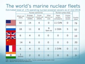
Source: two charts by author

In July 2018, I finished a complete update of the resource document and changed the title to, “Marine Nuclear Power: 1939 –2018.”  Due to its present size (over 2,100 pages), the resource document now consists of the following parts, all formatted as slide presentations:

  • Part 1: Introduction
  • Part 2A: United States – Submarines
  • Part 2B: United States – Surface Ships
  • Part 3A: Russia – Submarines
  • Part 3B: Russia – Surface Ships & Non-propulsion Marine Nuclear Applications
  • Part 4: Europe & Canada
  • Part 5: China, India, Japan and Other Nations
  • Part 6: Arctic Operations

The original 2015 resource document and this updated set of documents were compiled from unclassified, open sources in the public domain.

I acknowledge the great amount of work done by others who have published material in print or posted information on the internet pertaining to international marine nuclear propulsion programs, naval and civilian nuclear powered vessels, naval weapons systems, and other marine nuclear applications.  My resource document contains a great deal of graphics from many sources.  Throughout the document, I have identified the sources for these graphics.

You can access all parts of Marine Nuclear Power: 1939 – 2018 here:

Marine Nuclear Power 1939 – 2018_Part 1_Introduction

Marine Nuclear Power 1939 – 2018_Part 2A_USA_submarines

Marine Nuclear Power 1939 – 2018_Part 2B_USA_surface ships

Marine Nuclear Power 1939 – 2018_Part 3A_R1_Russia_submarines

Marine Nuclear Power 1939 – 2018_Part 3B_R1_Russia_surface ships & non-propulsion apps

Marine Nuclear Power 1939 – 2018_Part 4_Europe & Canada

Marine Nuclear Power 1939 – 2018_Part 5_China-India-Japan & Others

Marine Nuclear Power 1939 – 2018_Part 6 R1_Arctic marine nuclear

I hope you find this resource document informative, useful, and different from any other single document on this subject.  Below is an outline to help you navigate through the document.

Outline of Marine Nuclear Power:  1939 – 2018.

Part 1: Introduction

  • Quick look:  Then and now
  • State-of-the-art in 1955
  • Marine nuclear propulsion system basics
  • Timeline
    • Timeline highlights
    • Decade-by-decade
  • Effects of nuclear weapons and missile treaties & conventions on the composition and armament of naval fleets
  • Prospects for 2018 – 2030

Part 2A: United States – Submarines

  • Timeline for development of marine nuclear power in the US
  • US current nuclear vessel fleet
  • US naval nuclear infrastructure
  • Use of highly-enriched uranium (HEU) in US naval reactors
  • US submarine reactors and prototype facilities
  • US Navy nuclear-powered submarines
    • Nuclear-powered fast attack submarines (SSN)
      • Submarine-launched torpedoes, anti-submarine missiles & mines
      • Systems to augment submarine operational capabilities
    • Nuclear-powered strategic ballistic missile submarines (SSBN)
      • Submarine-launched strategic ballistic missiles (SLBMs)
    • Nuclear-powered guided missile submarines (SSGN)
      • Cruise missiles and other tactical guided missiles
    • Nuclear-powered special operations submarines

Part 2B: United States – Surface Ships

  • US naval surface ship reactors & prototype facilities
  • US Navy nuclear-powered surface ships
    • Evolution of the US nuclear-powered surface fleet
    • Nuclear-powered guided missile cruisers (CGN)
      • CGN tactical weapons
    • Nuclear-powered aircraft carriers (CVN)
      • Carrier strike group (CSG) & carrier air wing composition
  • Naval nuclear vessel decommissioning and nuclear waste management
  • US civilian marine nuclear vessels and reactors
    • Operational & planned civilian marine vessels and their reactors
    • Other US civilian marine reactor designs
  • Radioisotope Thermoelectric Generator (RTG) marine applications
  • US marine nuclear power current trends

Part 3A: Russia – Submarines

  • The beginning of the Soviet / Russian marine nuclear power program
  • Russian current nuclear vessel fleet.
  • Russian marine nuclear reactor & fuel-cycle infrastructure
  • Russian nuclear vessel design, construction & life-cycle infrastructure
  • Russian naval nuclear infrastructure
  • Russian nuclear-powered submarines
    • Submarine reactors
    • Nuclear-powered fast attack submarines (SSN)
      • Submarine-launched torpedoes & anti-submarine missiles
    • Strategic ballistic missile submarines (SSB & SSBN)
      • Submarine-launched ballistic missiles (SLBM)
    • Cruise missile submarines (SSG & SSGN).
      • Cruise missiles
    • Nuclear-powered special operations subs & strategic torpedoes
    • Other special-purpose nuclear-powered subs
    • Examples of un-built nuclear submarine projects

Part 3B: Russia – Surface Ships & Non-propulsion Marine Nuclear Applications

  • Russian nuclear-powered surface ships
    • Surface ship reactors
    • Nuclear-powered icebreakers
    • Nuclear-powered naval surface ships
      • Nuclear-powered guided missile cruisers
      • Nuclear-powered command ship
      • Nuclear-powered aircraft carrier
      • Nuclear-powered multi-purpose destroyer
  • Russian non-propulsion marine nuclear applications
    • Small reactors for non-propulsion marine nuclear applications
    • Floating nuclear power plants (FNPP)
    • Transportable reactor units (TRU)
    • Arctic seabed applications for marine nuclear power
    • Radioisotope Thermoelectric Generators (RTG)
  • Marine nuclear decommissioning and environmental cleanup
  • Russian marine nuclear power current trends

Part 4: Europe & Canada

  • Nations that operate or have operated nuclear vessels
    • United Kingdom
      • The beginning of the UK marine nuclear power program
      • UK current nuclear vessel fleet
      • UK naval nuclear infrastructure
      • UK naval nuclear reactors
      • UK Royal Navy nuclear-powered submarines
        • Nuclear-powered fast attack submarines (SSN)
          • Submarine-launched tactical weapons
        • Nuclear-powered strategic ballistic missile submarines (SSBN)
          • Submarine-launched ballistic missiles (SLBM)
      • UK disposition of decommissioned nuclear submarines
      • UK nuclear surface ship and marine reactor concepts
      • UK marine nuclear power current trends
    • France
      • The beginning of the French marine nuclear power program
      • French current nuclear vessel fleet
      • French naval nuclear infrastructure
      • French naval nuclear reactors
      • French naval nuclear vessels
        • Nuclear-powered strategic ballistic missile submarines (SNLE)
          • Submarine-launched ballistic missiles (MSBS)
        • Nuclear-powered fast attack submarines (SNA)
          • Submarine-launched tactical weapons
        • Nuclear-powered aircraft carrier
      • French disposition of decommissioned nuclear submarines
      • French non-propulsion marine reactor applications
      • French marine nuclear power current trends
    • Germany
  • Other nations with an interest in marine nuclear power technology
    • Italy
    • Sweden
    • Netherlands
    • Canada

Part 5: China, India, Japan and Other Nations

  • Nations that have operated nuclear vessels
    • China
      • The beginning of China’s marine nuclear power program
      • China’s current nuclear vessel fleet
      • China’s naval nuclear infrastructure
      • China’s nuclear vessels
        • Nuclear-powered fast attack submarines (SSNs)
          • Submarine-launched tactical weapons
        • Nuclear-powered strategic ballistic missile subs (SSBNs)
          • Submarine-launched ballistic missiles (SLBMs)
        • Floating nuclear power stations
        • Nuclear-powered surface ships
      • China’s decommissioned nuclear submarine status
      • China’s marine nuclear power current trends
    • India
      • The beginning of India’s marine nuclear power program
      • India’s current nuclear vessel fleet
      • India’s naval nuclear infrastructure
      • India’s nuclear-powered submarines
        • Nuclear-powered fast attack submarines (SSNs)
          • Submarine-launched tactical weapons
        • Nuclear-powered strategic ballistic missile submarines (SSBNs)
          • Submarine-launched ballistic missiles (SLBM).
      • India’s marine nuclear power current trends
    • Japan
  • Other nations with an interest in marine nuclear power technology
    • Brazil
    • North Korea
    • Pakistan
    • Iran
    • Israel
    • Australia

Part 6: Arctic Operations

  • Rationale for marine nuclear power in the Arctic
  • Orientation to the Arctic region
  • US Arctic policy
  • Dream of the Arctic submarine
  • US marine nuclear Arctic operations
  • UK marine nuclear Arctic operations
  • Canada marine nuclear ambitions
  • Russian marine nuclear Arctic operations
    • Russian non-propulsion marine nuclear Arctic applications
  • China’s marine nuclear ambitions
  • Current trends in marine nuclear Arctic operations

Periodic updates:

  • Parts 3A and 3B, Revision 1, were posted in October 2018
  • Part 6, Revision 1, was posted in February 2019

You Need to Know About Russia’s Main Directorate of Deep-Sea Research (GUGI)

Peter Lobner

The Main Directorate of Deep-Sea Research, also known as GUGI and Military Unit 40056, is an organizational structure within the Russian Ministry  of Defense that is separate from the Russian Navy.  The Head of GUGI is Vice-Admiral Aleksei Burilichev, Hero of Russia.

Source. Adapted from Ministry of Defense of the Russian Federation, http://eng.mil.ru/en/index.htm

Vice-Admiral Aleksei Burilichev at the commissioning of GUGI oceanographic research vessel Yantar. Source: http://eng.mil.ru/

GUGI is responsible for fielding specialized submarines, oceanographic research ships, undersea drones and autonomous vehicles, sensor systems, and other undersea systems.   Today, GUGI operates the world’s largest fleet of covert manned deep-sea vessels. In mid-2018, that fleet consisted of eight very specialized nuclear-powered submarines.

There are six nuclear-powered, deep-diving, small submarines (“nuclear deep-sea stations”), each of which is capable of working at great depth (thousands of meters) for long periods of time.  These subs are believed to have diver lockout facilities to deploy divers at shallower depths.

  • One Project 1851 / 18510 Nelma (aka X-Ray) sub delivered in 1986; Length: 44 m (144.4 ft.); displacement about 529 tons submerged. This is the first and smallest of the Russian special operations nuclear-powered submarines.
  • Two Project 18511 Halibut (aka Paltus) subs delivered between 1994 – 95; Length: 55 m (180.4 ft.); displacement about 730 tons submerged.
  • Three Project 1910 Kashalot (aka Uniform) subs delivered between 1986 – 1991, but only two are operational in 2018; Length: 69 m (226.4 ft.); displacement about 1,580 tons submerged.
  • One Project 09851 Losharik (aka NORSUB-5) sub delivered in about 2003; Length: 74 m (242.8 ft.); displacement about 2,100 tons submerged.

The trend clearly is toward larger, and certainly more capable deep diving special operations submarines.  The larger subs have a crew complement of 25 – 35.

Kashalot notional cross-section diagram. Source: adapted from militaryrussia.ru

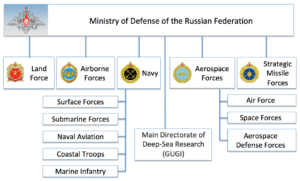
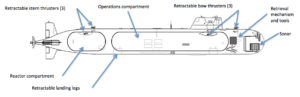
Kashalot notional diagram showing deployed positioning thrusters, landing legs and tools for working on the bottom. Source: http://nvs.rpf.ru/nvs/forum

The Russian small special operations subs may have been created in response to the U.S. Navy’s NR-1 small, deep-diving nuclear-powered submarine, which entered service in 1969.  NR-1 had a length of 45 meters (147.7 ft.) and a displacement of about 400 tons submerged, making it roughly comparable to the Project 1851 / 18510 Nelma . NR-1 was retired in 2008, leaving the U.S. with no counterpart to the Russian fleet of small, nuclear-powered special operations subs.

GUGI operates two nuclear-powered “motherships” (PLA carriers) that can transport one of the smaller nuclear deep-sea stations to a distant site and provide support throughout the mission. The current two motherships started life as Delta III and Delta IV strategic ballistic missile submarines (SSBNs).  The original SSBN missile tubes were removed and the hulls were lengthened to create large midship special mission compartments with a docking facility on the bottom of the hull for one of the small, deep-diving submarines.  These motherships probably have a test depth of about 250 to 300 meters (820 to 984 feet).  They are believed to have diver lockout facilities for deploying divers.

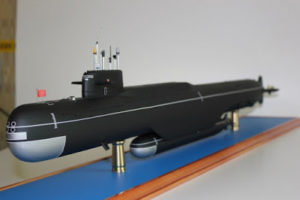
General arrangement of a Russian mothership carrying a small special operations submarine.  Source:  http://gentleseas.blogspot.com/2015/08/russias-own-jimmy-carter-special-ops.html

Delta-IV mothership carrying Losharik.  Source: GlobalSecurity.org

The motherships also are believed capable of deploying and retrieving a variety of  autonomous underwater vehicles (AUVs), including the relatively large Harpsichord: Length: 6.5 m (21.3 ft.); Diameter 1 m (3.2 ft.); Weight: 3,700 kg (8,157 pounds).

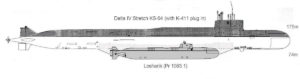
Harpsichord-2R-PM. Source: http://vpk-news.ru/articles/30962

The following graphic shows a mothership carrying a small special operations sub  while operating with a Harpsichord AUV.

                       Source: https://russianmilitaryanalysis.wordpress.com/tag/9m730/

These nuclear submarines are operated by the 29th Special Submarine Squadron, which is based along with other GUGI vessels at Olenya Bay, in the Kola Peninsula on the coast of the Barents Sea.

Olenya Bay is near Murmansk.  Source: Google Maps

Russian naval facilities near Murmansk.  Source: https://commons.wikimedia.org

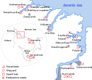
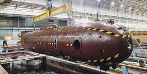
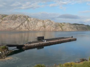
Mothership BS-136 Orenburg at Oleyna Bay.  Source: Source: http://www.air-defense.net/

The GUGI fleet provides deep ocean and Arctic operating capabilities that greatly exceed those of any other nation.  Potential missions include:

  • Conducting subsea surveys, mapping and sampling (i.e., to help validate Russia’s extended continental shelf claims in the Arctic; to map potential future targets such as seafloor cables)
  • Placing and/or retrieving items on the sea floor (i.e., retrieving military hardware, placing subsea power sources, power distribution systems and sonar arrays)
  • Maintaining military subsea equipment and systems
  • Conducting covert surveillance
  • Developing an operational capability to deploy the Poseidon strategic nuclear torpedo.
  • In time of war, attacking the subsea infrastructure of other nations in the open ocean or in the Arctic (i.e., cutting subsea internet cables, power cables or oil / gas pipelines)

Analysts at the firm Policy Exchange reported that the world’s undersea cable network comprises about 213 independent cable systems and 545,018 miles (877,121 km) of fiber-optic cable.  These undersea cable networks carry an estimated 97% of global communications and $10 trillion in daily financial transactions are transmitted by cables under the ocean.

Since about 2015, NATO has observed Russian vessels stepping up activities around undersea data cables in the North Atlantic. None are known to have been tapped or cut.  Selective attacks on this cable infrastructure could electronically isolate and severely damage the economy of individual countries or regions.  You’ll find a more detailed assessment on this matter in the 15 December 2017 BBC article, “Russia a ‘risk’ to undersea cables, Defence chief warns.”

http://www.bbc.com/news/uk-42362500

GUGI also is responsible for the development of the Poseidon (formerly known as Status-6 / Kanyon) strategic nuclear torpedo and the associated “carrier” submarines.

Poseidon, which was first revealed on Russian TV in November 2015,  is a large, nuclear-powered, autonomous underwater vehicle (AUV) that functionally is a giant, long-range torpedo.

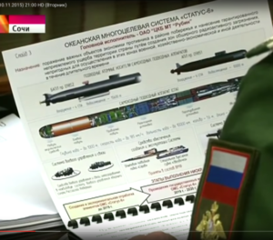
 The Russian TV “reveal” of the Oceanic Multipurpose System Status-6 November 2015. Source: https://russianmilitaryanalysis.wordpress.com/tag/9m730/

It is capable of delivering a very large nuclear warhead (perhaps up to 100 MT) underwater to the immediate proximity of an enemy’s key economic and military facilities in coastal areas.  It is a weapon of unprecedented destructive power and it is not subject to any existing nuclear arms limitation treaties. However, its development would give Russia leverage in future nuclear arms limitation talks.

The immense physical size of the Poseidon strategic nuclear torpedo is evident in the size comparison chart below.

Source: http://www.hisutton.com/

The Bulava is the Russian submarine launched ballistic missile (SLBM) carried on Russia’s modern Borei-class SSBNs.  The UGST torpedo is representative of a typical torpedo launched from a 533 mm (21 inch) torpedo tube, which is found on the majority of submarines in the world.  An experimental submarine, the B-90 Sarov, appears to be the current testbed for the Poseidon strategic torpedo.  Russia is building other special submarines to carry several Poseidon strategic torpedoes.  One is believed to be the giant, highly modified Oscar II submarine K-139 Belgorod, which also will serve as a mothership for a small, special operations nuclear sub.  The other is the smaller Project 09851 submarine Khabarovsk, which appears to be purpose-built for carrying the Poseidon.

For more information on GUGI, Russian special operations submarines and other covert underwater projects, refer to the Covert Shores website created by naval analyst H. I. Sutton, which you’ll find at the following link:

http://www.hisutton.com/Analysis%20-%20Russian%20Status-6%20aka%20KANYON%20nuclear%20deterrence%20and%20Pr%2009851%20submarine.html