Category Archives: Physics

The Fork in the Road to Electric Power From Fusion

Peter Lobner, 1 February 2021

This article provides a brief overview of the “mainstream” international plans to deliver the first large tokamak commercial fusion power plant prototype in the 2060 to 2070 timeframe.  Then we’ll take a look at alternate plans that could lead to smaller and less expensive commercial fusion power plants being deployed much sooner, perhaps in the 2030s. These alternate plans are enabled by recent technical advances and a combination of public and private funding for many creative teams that are developing and testing a diverse range of fusion machines that may be developed in the near-term into compact, relatively low-cost fusion power plants.  

This article includes links in Section 6 to a set of supporting articles that provide details on 18 fusion power reactor development projects, mostly at private firms. You can download a pdf copy of this main article here: https://lynceans.org/wp-content/uploads/2021/02/The-Fork-in-the-Road-to-Electric-Power-From-Fusion-converted_1.pdf

1. Plodding down the long road to controlled nuclear fusion with ITER

Mainstream fusion development is focused on the construction of the International Thermonuclear Experimental Reactor (ITER), which is a very large magnetic confinement fusion machine.  The 35-nation ITER program describes their reactor as follows:  “Conceived as the last experimental step to prove the feasibility of fusion as a large-scale and carbon-free source of energy, ITER will be the world’s largest tokamak, with ten times the plasma volume of the largest tokamak operating today.” ITER is intended “to advance fusion science and technology to the point where demonstration fusion power plants can be designed.”

ITER is intended to be the first fusion experiment to produce a net energy gain (“Q”) from fusion.  Energy gain is the ratio of the amount of fusion energy produced (Pfusion) to the amount of input energy needed to create the fusion reaction (Pinput).  In its simplest form, “breakeven” occurs when Pfusion = Pinput and Q = 1.0.  The highest value of Q achieved to date is 0.67, by the Joint European Torus (JET) tokamak in 1997.The ITER program was formally started with the ITER Agreement, which was signed on 21 November 2006.  

Nations contributing to the manufacture of major ITER 
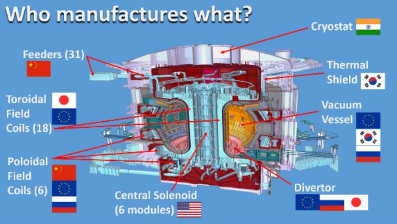
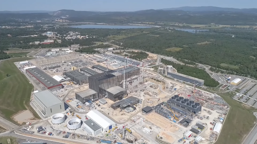
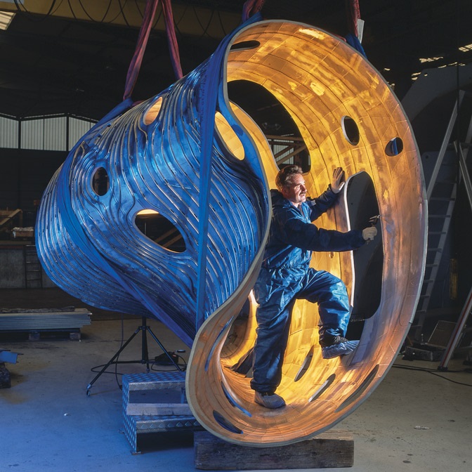
components.  Source: SciTechDaily (28 Jul 2020)

The official start of the “assembly phase” of the ITER reactor began on 28 July 2020. The target date of “first plasma” currently is in Q4, 2025.  At that time, the reactor will be only partially complete.  During the following ten years, construction of the reactor internals and other systems will be completed along with a comprehensive testing and commissioning program. The current goal is to start experiments with deuterium / deuterium-tritium (D/D-T) plasmas in December 2035.  

After initial experiments in early 2036, there will be a gradual transition to fusion power production over the next 12 – 15 months.  By mid-2037, ITER may be ready to conduct initial high-power demonstrations, operating at several hundred megawatts of D-T fusion power for several tens of seconds.  This milestone will be reached more than 30 years after the ITER Agreement was signed.

Subsequent experimental campaigns will be planned on a two-yearly cycle. The principal scientific mission goals of the ITER project are:

  • Produce 500 MW of energy from fusion while using only 50 MW of energy for input heating, yielding Q ≥ 10
  • Demonstrate Q ≥ 10 for burn durations of 300 – 500 seconds (5.0 – 8.3 minutes)
  • Demonstrate long-pulse, non-inductive operation with Q ~ 5 for periods of up to 3,000 seconds (50 minutes).

All that energy will get absorbed in reactor structures, with some of it being carried off in cooling systems.  However, ITER will not generate any electric power from fusion.  

The total cost of the ITER program currently is estimated to be about $22.5 billion. In 2018, Reuters reported that the US had given about $1 billion to ITER so far, and was planning to contribute an additional $500 million through 2025. In Fiscal Year 2018 alone, the US contributed $122 million to the ITER project.

You’ll find more information on the ITER website, including a detailed timeline, at the following link: https://www.iter.org

The ITER site in 2020, being built next to the Cadarache facility in Saint-Paul-lès-Durance, in Provence, southern France.  Source: Macskelek via Wikipedia

2.  Timeline for a commercial fusion power plant based on ITER

In December 2018, a National Academy of Sciences, Engineering & Medicine (NASEM) committee issued a report that included the following overview of timelines for fusion power deployment based on previously studied pathways for developing fusion power plants derived from ITER. The timelines for the USA, South Korea, Europe, Japan and China are shown below.

Source: “A Strategic Plan for U.S. Burning
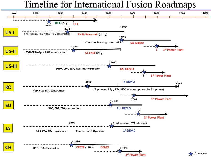
Plasma Research” (NASEM, 2019)

All of the pathways include plans for a DEMO fusion power plant (i.e., a prototype with a power conversion system) that would start operation between 2050 and 2060.  Based on experience with DEMO, the first commercial fusion power plants would be built a decade or more later. You can see that, in most cases, the first commercial fusion power plant is not projected to begin operation until the 2060 to 2070 timeframe.

3. DOE is helping to build a fork in the road

Fortunately, a large magnetic confinement tokamak like ITER is not the only route to commercial fusion power.  However, ITER currently is consuming a great deal of available resources while the promise of fusion power from an ITER-derived power plant remains an elusive 30 years or more away, and likely at a cost that will not be commercially viable.  

Since the commitment was made in the early 2000s to build ITER, there have been tremendous advances in power electronics and advanced magnet technologies, particularly in a class of high temperature superconducting (HTS) magnets known as rare-earth barium copper oxide (REBCO) magnets that can operate at about 90 °K (-297 °F), which is above the temperature of liquid nitrogen (77 °K; −320 °F). These technical advances contribute to making ITER obsolete as a path to fusion power generation.

A 2019 paper by Martin Greenwald describes the relationship of constant fusion gain (Q = Pfusion / Pinput) to the magnetic field strength (B) and the plasma radius (R) of a tokamak device.  As it turns out, Q is proportional to the product of B and R, so, for a constant gain, there is a tradeoff between the magnetic field strength and the size of the fusion device. This can be seen in the comparison between the relative field strengths and sizes of ITER and ARC (a tokomak being designed now), which are drawn to scale in the following chart. 

 
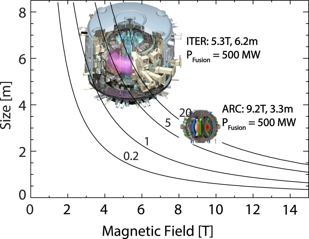
Contours of constant fusion gain (Q) plotted against magnetic field strength (T, Tesla) and device size (plasma radius in meters): Source: Greenwald (2019)

ITER has lower field strength conventional superconducting magnets and is much larger than ARC, which has much higher field strength HTS magnets that enable its compact design. Greenwald explains, “With conventional superconductors, the region of the figure above 6T was inaccessible; thus, ITER, with its older magnet technology, is as small as it could be.” So, ITER will be a big white elephant, useful for scientific research, but likely much less useful on the path to fusion power generation than anyone expected when they signed the ITER Agreement in 2006.

For the past decade, there has been increasing interest in, and funding for, developing lower cost, compact fusion power plants using any fusion technology that can deliver a useful power generation capability at an commercially viable cost. Department of Energy’s (DOE) Advanced Research Project Agency – Energy (ARPA-E) has recommended the following cost targets for such a commercial fusion power plant:

Overnight capital cost of < US $2 billion and < $5/W

At $5/W, the upper limit would be a 400 MWe fusion power plant.

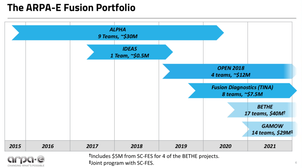
Since 2014, DOE has created a series of funding programs for fusion R&D projects to support development of a broad range of compact, low-cost fusion power plant design concepts.  This was a significant change for the DOE fusion program, which has been contributing to ITER and a whole range of other fusion-related projects, but without a sense of urgency for delivering the technology needed to develop and operate commercial fusion power plants any time soon.  Now, a small part of the DOE fusion budget is focused on resolving some of the technical challenges and de-risking the path forward sooner rather than later, and thereby improving the investment climate to the point that investors become willing to contribute to the development of small, low-cost fusion power plants that may be able to produce electrical power within the next decade or two.

These DOE R&D programs are administered ARPA-E and the Office of Science, Fusion Energy Sciences (FES).

  • ARPA-E advances high-potential, high-impact energy technologies that are too early for private-sector investment. The ARPA-E fusion R&D programs are named ALPHA, IDEAS, BETHE, TINA and GAMOW. ARPA-E jointly funds the GAMOW fusion R&D program and part of the BETHE program with FES. In addition, the ARPA-E OPEN program makes R&D investments in the entire spectrum of energy technologies, including fusion.
  • FES is the largest US federal government supporter of research that is addressing the remaining obstacles to commercial fusion power.  The FES fusion R&D program is named INFUSE. In addition FES jointly funds GAMOW and part of BETHE with ARPA-E.

Here’s an overview of these DOE programs.

DOE ARPA-E ALPHA program (2015 – 2020)

In 2015, ARPA-E initiated a five-year, $30 million research program into lower-cost approaches to producing electric power from fusion.  This was known as the ALPHA program (Accelerating Low-Cost Plasma Heating and Assembly). The goal was to expand the range of potential technical solutions for generating power from fusion, focusing on small, low-cost, pulsed magneto-inertial fusion (MIF) devices.  

The ARPA-E ALPHA program home page is here: https://arpa-e.energy.gov/technologies/programs/alpha

There were nine program participants in the ALPHA program. Helion Energy ($3.97 million) and MIFTI ($4.60 million) were among the private fusion reactor firms receiving ALPHA awards.  Los Alamos National Laboratory (LANL) received $6.63 million to fund the Plasma Liner Experiment (PLX-α) team, which included the private firm HyperV Technologies Corp.

In 2018, ARPA-E asked JASON to assess its accomplishments on the ALPHA program and the potential of further investments in this field.  Among their findings, JASON reported that MIF is a physically plausible approach to controlled fusion and, in spite of very modest funding to date, some particular approaches are within a factor of 10 of scientific break-even.  JASON also recommended supporting all promising approaches, while giving near-term priority to achieving breakeven (Q ≥ 1) in a system that can be scaled up to be commercial power plant. You can read the November 2018 JASON report here: https://fas.org/irp/agency/dod/jason/fusiondev.pdf

DOE ARPA-E IDEAS program (2017 – 2019)

The ARPA-E IDEAS program (Innovative Development in Energy-Related Applied Science) provides support of early-stage applied research to explore pioneering new concepts with the potential for transformational and disruptive changes in any energy technology. IDEAS awards are restricted to a maximum of $500,000 in funding.  There have been 59 IDEAS awards for a broad range of energy-related technologies, largely to national laboratories and universities.

The IDEAS program home page is here: https://arpa-e.energy.gov/technologies/programs/ideas

There was one fusion-related IDEAS award to the University of Washington ($482 k).

DOE ARPA-E OPEN program (2018)

In 2018, ARPA-E issued its fourth OPEN funding opportunity designed to catalyze transformational breakthroughs across the entire spectrum of energy technologies, including fusion.  OPEN 2018 is a $199 million program funding 77 projects. 

The OPEN 2018 program home page is here: https://arpa-e.energy.gov/technologies/open-programs/open-2018

Four fusion-related projects were funded for a total of about $12 million.  ZAP Energy ($6.77 million), CTFusion ($3.0 million) and Princeton Fusion Systems ($1.1 million) were among the private fusion reactor firms receiving OPEN 2018 awards.

DOE ARPA-E TINA Fusion Diagnostics program (2019 – 2021)

The TINA program established diagnostic “capability teams” to support state-of-the-art diagnostic system construction/deployment and data analysis/interpretation on ARPA-E-supported fusion experiments.  This program awarded $7.5 million to eight teams, primarily from national laboratories and universities.

DOE ARPA-E BETHE program (2020 – 2024)

DOE’s ARPA-E also runs the BETHE program (Breakthroughs Enabling THermonuclear-fusion Energy), which is a $40 million program that aims to deliver a large number of lower-cost fusion concepts at higher performance levels. BETHE R&D is focused in the following areas:

  • Concept development to advance the performance of inherently lower cost but less mature fusion concepts.
  • Component technology development that could significantly reduce the capital cost of higher cost, more mature fusion concepts.
  • Capability teams to improve/adapt and apply existing capabilities (e.g., theory/modeling, machine learning, or engineering design/fabrication) to accelerate the development of multiple concepts.

FES contributes $5 million to BETHE program funding for component technology development. The BETHE program home page is here: https://arpa-e.energy.gov/technologies/programs/bethe

Sixteen research projects were awarded on 7 April 2020. Brief project descriptions are available here: https://arpa-e.energy.gov/sites/default/files/documents/files/BETHE_Project_Descriptions_FINAL.24.20.pdf

ZAP Energy ($1 million) and Commonwealth Fusion Systems ($2.39 million) were among the private fusion reactor firms directly receiving BETHE awards. 

The following awards were made to universities or national laboratories working with teams that include a significant role for a private fusion reactor firm: 

  • University of Washington received $1.5 million for improving IDCD plasma control, which is applicable to their collaborative work with CTFusion on the Dynomak fusion reactor concept.
  • LANL received $4.62 million to fund the Plasma Liner Experiment (PLX-α) team, which includes HyperJet

DOE ARPA-E / FES GAMOW program (2020 – 2024)

Yet another DOE funding program for fusion research is named GAMOW (Galvanizing Advances in Market-Aligned Fusion for an Overabundance of Watts), which is a $29 million program announced in February 2020.  GAMOW is jointly funded and overseen by ARPA-E and FES.  GAMOW program focuses on the following three areas:

  • Technologies and subsystems between the fusion plasma and balance of plant.
  • Cost-effective, high-efficiency, high-duty-cycle driver technologies.
  • Crosscutting areas such as novel fusion materials and advanced in additive manufacturing for fusion-relevant materials and components.

The GAMOW program home page is here: https://arpa-e.energy.gov/technologies/programs/gamow

In September 2020, ARPA-E announced 14 projects, primarily for national laboratory and university participants that were funded under the GAMOW program. Brief project descriptions are available here: https://arpa-e.energy.gov/sites/default/files/documents/files/GAMOW_Project_Descriptions_FINAL_9.2.20.pdf

Princeton Fusion Systems ($1.1 million) was among the private fusion reactor firms receiving GAMOW awards.

DOE FES INFUSE program (2020 – present)

The DOE FES INFUSE program (Innovation Network for Fusion Energy) was created to “accelerate fusion energy development in the private sector by reducing impediments to collaboration involving the expertise and unique resources available at DOE laboratories.” ….”DOE-FES will accept basic research applications focused on innovation that support production and utilization of fusion energy (e.g., for generation of electricity, supply of process heat, etc.)….”

In Fiscal Years 2020 and 2021, the INFUSE program annual budget was $4 million. INFUSE is a cost sharing program with DOE-FES funding 80% of a project’s cost and the award recipient funding the remaining 20%. The DOE-FES INFUSE program home page is here: https://infuse.ornl.gov

So far, there have been three rounds of INFUSE awards.  I think you will find that it is much more difficult to find detailed information on the DOE FES INFUSE awards, which are administered by Oak Ridge National Laboratory (ORNL), than it is to find information on any of the DOE ARPA-E program.  Here’s a brief INFUSE summary.

  • 1st round FY 2020: On 15 October 2019, DOE announced the first INFUSE awards, which provided funding for 12 projects with representation from six private companies partnering with six national laboratories.  The six private firms included:  Commonwealth Fusion Systems (4 awards) and TAE Technologies, Inc. (3 awards)
  • 2nd round FY 2020: On 3 September 2020, DOE announced funding for 10 projects.  The private firms included:  Commonwealth Fusion Systems (3 awards), TAE Technologies, Inc. (1 award), Tokamak Energy, Inc. (UK, 3 awards), and General Fusion Corp. (Canada, 1 award).
  • 1st round FY 2021: On 3 December 2020, DOE announced funding 10 projects in a second round of FY 2021 INFUSE awards. The private firms receiving awards included:  Commonwealth Fusion Systems (1 award), General Fusion Corp. (Canada, 1 award), MIFTI (1 award), Princeton Fusion Systems (1 award), TAE Technologies, Inc. (2 awards), Tokamak Energy, Inc. (UK, 2 awards).

DOE-FES has issued a call for new proposals for FY 2021 INFUSE awards. The closing date for submissions is 26 February 2021.

DOE SBIR and STTR programs

The DOE Small Business Innovation Research (SBIR) and Small Business Technology Transfer (STTR) programs develop innovative techniques, instrumentation, and concepts that have applications to industries in the private sector, including in the fusion sector. The SBIR / STTR home page is here:  https://www.energy.gov/science/sbir/small-business-innovation-research-and-small-business-technology-transfer

Fusion-related awards are listed here: https://science.osti.gov/sbir/Research-Areas-and-Impact#FES

The DOE grand total

So far, these ARPA-E and FES programs have committed about $127 million in public funds to 77 different projects between 2014 and 2021.  While some of the awards are sizeable ($5 – 6 million), many are very modest awards. The DOE total for all small (non-mainstream) fusion projects over a seven year period is about the same amount as the annual US contribution to the ITER program, which isn’t going lead to a fusion power plant in my lifetime, if ever.

While DOE has been kind enough to create the fork in the road, they do not have the deployable financial resources to push on to the next step of actually building prototypes of commercial fusion power plants in the near term. 

4.  A roadmap for achieving commercial fusion sooner

In 2019 and 2021, the National Academies and DOE-FES, respectively, published the recommendations of committees that were charged with defining the path(s) forward for the US to achieve commercial fusion power.  In both cases, the committee recommended continued support for ITER while urging the US to proceed with a separate national program that encourages and supports public-private partnerships to build compact power plants that produce electricity from fusion at the lowest possible capital cost.  These committee reports are briefly summarized below. 

National Academies: “Final Report of the Committee on a Strategic Plan for U.S. Burning Plasma Research” (2019)

In December 2018, a National Academy of Sciences, Engineering & Medicine (NASEM) committee issued a report entitled, “A Strategic Plan for U.S. Burning Plasma Research.” 

As noted previously, the NASEM report described the current path forward based on power plants derived largely from ITER technology.  On this path, the first commercial fusion power plant is not projected to begin operation until the 2060 to 2070 timeframe.

The NASEM committee report is very important because it defines an alternate pathway (i.e., the fork in the road) that could deliver fusion power considerably sooner and at much lower capital cost. 

The committee offered the following recommendations:

  • The US should remain an ITER partner.  This is the most cost-effective way to gain experience with burning plasma at the scale of a power plant.  However:
    • Significant R&D is required in addition to ITER to produce electricity from this type of fusion reactor.
    • ITER is too large and expensive to be economically competitive in the US market when compared to other carbon-neutral energy technologies.
  • The US should start a national program of accompanying research and technology leading to the construction of a compact pilot power plant that produces electricity from fusion at the lowest possible capital cost.
    • Emphasize developing innovative, world-leading solutions.
    • Effective application of US near-term R&D investments is critical, as other nations continue to invest in new fusion facilities that advance their own approaches.

You can read the NASEM report here: https://www.nationalacademies.org/our-work/a-strategic-plan-for-us-burning-plasma-research

DOE FES: “Powering the Future – Fusion & Plasmas”  (2021)

In January 2021, DOE FES published a draft report from their Fusion Energy Sciences Advisory Committee (FESAC) entitled “Powering the Future – Fusion & Plasmas.”  This draft report supports the NASEM committee recommendations and concluded that there are two viable paths to commercial fusion power:

  • Partnership in the ITER fusion project is essential for US fusion energy development, as is supporting the continued growth of the private sector fusion energy industry. 
  • Public-private partnerships have the potential to reduce the time required to achieve commercially viable fusion energy. 
  • The fusion pilot plant goal requires “a pivot toward research and development of fusion materials and other needed technology.” Several new experimental facilities were recommended.

You can read the complete draft FESAC report here: https://science.osti.gov/-/media/fes/fesac/pdf/2020/202012/DRAFT_Fusion_and_Plasmas_Report_120420.pdf

As of late January 2021, the FESAC final report was in preparation.   When available, it will be posted here:  http://usfusionandplasmas.org

Funding at the fork in the road

At the fork in the road, the US will be hedging its bets and taking both paths, continuing to support ITER at the current level (about $125 million/year) while building new fusion experimental facilities and trying to place a stronger emphasis on timely development of compact fusion power plants through public-private partnerships as well as infusions of private capital.  

In the years ahead, the DOE FES fusion budget is expected to be essentially flat, with growth at just a modest rate of 2%/year being among the likely range of budget scenarios.  At the same time, FES will attempt to launch several new major fusion R&D facilities and related programs, as recommended by FESAC.

Without a significantly bigger budget authorization from Congress, the FES budget becomes a zero sum game.  To create the budget for any of these new R&D facilities and programs, other part of the FES budget have to lose. In this constrained budget environment, I think FES funding for compact fusion power plant development will find stiff competition and will not be on a growth path.

Recall that ARPA-E’s role is to advance high-potential, high-impact energy technologies that are too early for private-sector investment. When major risk issues for a particular fusion reactor concept have been resolved to an appropriate level, funding from ARPA-E may be redirected to other higher risk matters waiting to be addressed.  

While the NASEM and FESAC reports support public-private partnerships, the sheer magnitude of the funds required (many billions of dollars) to develop several small prototype fusion power plant designs in parallel exceeds DOE’s ability to fund the deals at the same level as the current 80% (DOE) / 20% (private) partnership deals.  The FES annual budget for the past three years has been quite modest: $564 million (FY2019 enacted), $671 million (FY2020 enacted) and $425 million (FY2021 requested).

Making real progress toward deployment of operational fusion power plants will depend on billions of dollars in private / institutional capital being invested in the firms that will design and build the first small commercial fusion power plants.  

I think DOE and the commercial fusion power industry are in a similar position to NASA and the commercial spaceflight industry two decades ago when Blue Origin (Jeff Bezos, 2000) and SpaceX (Elon Musk, 2002) were founded.  At that time, the traditional route to space was via NASA.  Two decades later, it’s clear that many commercial firms and their investors have contributed to building a robust low Earth orbit spaceflight industry that could never have been developed in that short time frame with NASA’s limited budget.  In the next two decades, I think the same type of transition needs to occur in the relationship between DOE and the private sector fusion industry if we expect to reap the benefits of clean fusion power soon.  It’s time for FES and the commercial fusion industry to confirm that they share a vision and a common aggressive timeline for bringing small commercial fusion power plants to the market.  That point doesn’t come across in the FESAC report.

Private and institutional investors already making major investments in the emerging fusion energy market.  As you might expect, some fusion firms have been much more successful than others in raising funds.  You’ll find a summary of publically available funding information on the Fusion Energy Base website here: https://www.fusionenergybase.com/organization/commonwealth-fusion-systems

5. The US Navy also may be building a fork in the road

The Navy has been quietly developing its own concepts for compact fusion power plants.  We’ll take a look at three recent designs. Could the Navy wind up being an important contributor to the development and deployment of commercial fusion power plants? 

6. The race is on to beat ITER with smaller, lower-cost fusion

In this section, we’ll take a look at the status of the following small fusion power plant development efforts, mostly by private companies. 

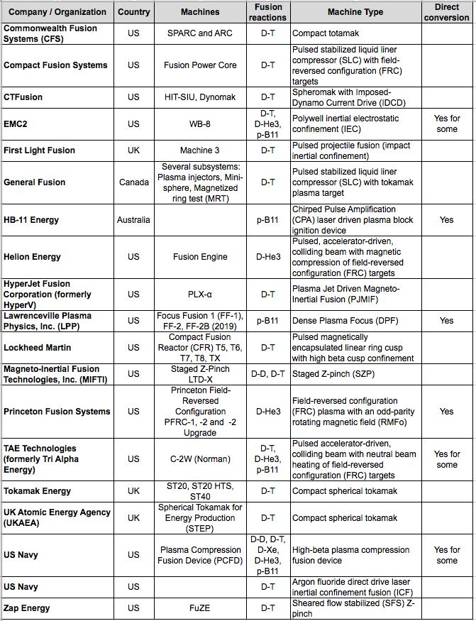
Collectively, they are applying a diverse range of technologies to the challenge of generating useful electric power from fusion at a fraction of the cost of ITER.  Based on claims from the development teams, it appears that some of the compact fusion reactor designs are quite advanced and probably will be able to demonstrate a net energy gain (Q > 1.0) in the 2020s, well before ITER. 

You’ll find details on these 18 organizations and their fusion reactor concepts in my separate articles at the following links:

7.  Conclusions

There certainly are many different technical approaches being developed for small, lower-cost fusion power plants. Several teams are reporting encouraging performance gains that suggest that their particular solutions are on credible paths toward a fusion power plant. However, as of January 2021, none of the operating fusion machines have achieved breakeven, with Q = 1.0, or better.  It appears that goal remains at least a few years in the future, even for the most advanced contenders.

The rise of private funding and public-private partnerships is rapidly improving the resources available to many of the contenders.  Good funding should spur progress for many of the teams.  However, don’t be surprised if one or more teams wind up at a technical or economic dead end that would not lead to a commercially viable fusion power plant. Yes, I think ITER is heading down one of those dead ends right now.

So, where does that leave us?  The promise for success with a small, lower-cost fusion power plant is out there, and such power plants should win the race by a decade or more over an ITER-derived fusion power plant.  While there are many contenders, which ones are the leading contenders for deploying a commercially viable fusion power plant?

To give some perspective, it’s worth taking a moment to recall the earliest history of the US commercial nuclear power industry, which is recounted in detail for the period from 1946 – 1963 by Wendy Allen in a 1977 RAND report and summarized in the following table.

US fission demonstration power plants. Source: RAND R-2116-NSF

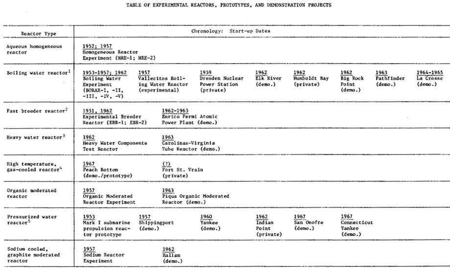
The main points to recognize from the RAND report are:

  • Eight different types of fission reactors were built as demonstration plants and tested. All of the early reactors were quite small in comparison to later nuclear power plants.
  • Some were built on Atomic Energy Commission (AEC, now DOE) national laboratory sites and operated as government-owned proof-of-principle reactors.  The others were licensed by the AEC (now the Nuclear Regulatory Commission, NRC) and operated by commercial electric power utility companies.  These reactors were important for building the national nuclear regulatory framework and the technical competencies in the commercial nuclear power and electric utility industries.
  • In the long run, only two reactor designs survived the commercial test of time and proved their long-term financial viability:  the pressurized water reactor (PWR) and the boiling water reactor (BWR), which are the most common types of fission power reactors operating in the world today.

See RAND report R-2116-NSF for more information of the early US commercial fission reactor demonstration plant programs here: https://www.rand.org/pubs/reports/R2116.html

With the great variety of candidate fusion power plant concepts being developed today, we simply don’t know which ones will be the winners in a long-term competition, except to say that an ITER-derived power plant will not be among the winners.  What we need is a national demonstration plant program for small fusion reactors.  This means we need the resources to build and operate several different fusion power reactor designs soon and expect that the early operating experience will quickly drive the evolution of the leading contenders toward mature designs that may be successful in the emerging worldwide market for fusion power. The early fission reactor history shows that we should expect that some of the early fusion power plant designs won’t survive in the long-term fusion power market, for a variety of reasons.

Matthew Moynihan, in his 2019 article, “Selling Fusion in Washington DC,” on The Fusion Podcast website, offered the following approach, borrowed from the biotech industry, to build a pipeline of credible projects while driving bigger investments into the more mature and more promising programs. Applying this approach to the current hodgepodge of DOE fusion spending would yield more focused spending of public money toward the goal of delivering small fusion power plants as soon as practical. The actual dollar amounts in the following chart can be worked out, but I think the basic principle is solid.

Source: The Fusion Podcast, 12 January 2019

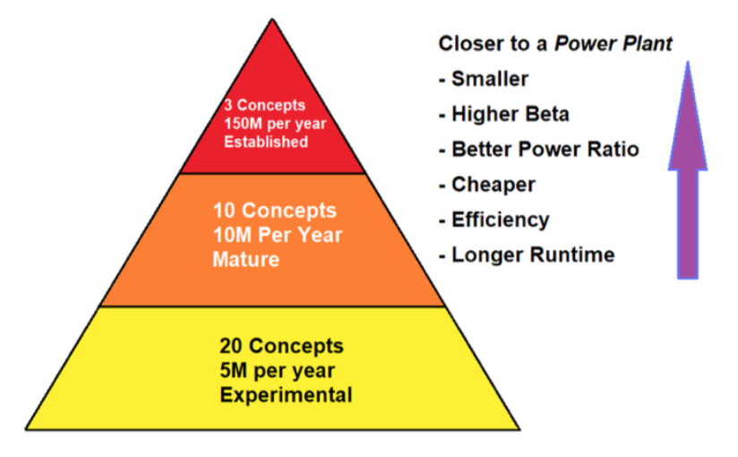
With this kind of focus from DOE, the many contenders in the race to build a small fusion power plant could be systematically ranked on several parameters that would make their respective technical and financial risks more understandable to everyone, especially potential investors.  With an unbiased validation of relative risks from DOE, the leading candidates in the US fusion power industry should be able to raise the billions of dollars that will be needed to develop their designs into the first wave of demonstration fusion power plants, like the US fission power industry did 60 to 70 years ago.

Perhaps Carly Anderson had the right idea when she suggested Fantasy Fusion as a way to introduce some fun into the uncertain world of commercial fusion power development and investment.  You can read her September 2020 article here: https://medium.com/prime-movers-lab/fantasy-fusion-77621cc901e2

If you believe we’re coming into the home stretch, it’s not too late to place a real bet by actually investing in your favorite fusion team(s).  It is risky, but the commercial fusion power trophy will be quite a prize!  I’m sure it will come with some pretty big bragging rights.

8. For more information

General

ITER

DOE ALPHA Program

DOE ARPA-E IDEAS program (2017 – 2019)

DOE BETHE Program

DOE GAMOW Program

DOE INFUSE Program

CNO Fusion Cycle in the Sun Confirmed by Borexino

Peter Lobner, 26 November 2020

Background

Fusion reactions in our Sun are predominately proton – proton reactions that lead to the production of the light elements helium, lithium, beryllium and boron.  The next step up on the periodic table of elements is carbon.

Carbon is formed in our Sun by the “triple alpha” process shown in the following diagram.  First, two helium-4 nuclei (4He, an alpha particles) fuse, emit a gamma ray and form an atom of unstable beryllium-8 (8Be), which can fuse with another helium nucleus, emit another gamma ray and form an atom of stable carbon-12 (12C). Timing is everything, because that fusion reaction must occur during the very short period of time before the unstable beryllium-8 atom decays (half life is about 8.2 x 10⁻¹⁷ seconds).  

Stellar process for producing carbon-12.  Source:  Borb via Wikipedia

Stellar process for producing carbon-12.  Source:  Borb via Wikipedia

The carbon produced by the above reaction chain is the starting point for the carbon-nitrogen-oxygen (CNO) fusion cycle, which accounts for about 1% of the fusion reactions in a relatively small star the size of our Sun.  In larger stars, the CNO cycle becomes the dominant fusion cycle.

The In the following diagram, the CNO cycle starts at the top-center:

  • First, an atom of stable carbon-12 (12C) captures a proton (1H) and emits a gamma ray (γ), producing an atom of nitrogen-13 (13N), which has a half-life of almost 10 minutes.  
  • The cycle continues  when the atom of nitrogen-13 decays into an atom of stable carbon-13 (13C) and emits a neutrino (ν) and a positron (β+).  
  • When the carbon-13 atom captures of a proton, it emits a gamma ray and produces an atom of stable nitrogen-14 (14N).  
  • When the nitrogen-14 atom captures a proton, it emits a gamma ray and produces an atom of oxygen-15 (15O), which has a half-life of almost 71 seconds.
  • The cycle continues  when the atom of oxygen-15 decays into an atom of stable nitrogen-15 (15N) and emits a neutrino (ν) and a positron (β+).  
  • After one more proton capture, the nitrogen-15 atom splits into a helium nucleus (4He) and an atom of stable carbon-12, which is indistinguishable from the carbon-12 atom that started the cycle.
The carbon-nitrogen-oxygen (CNO) cycle.  
Source:  Borb via Wikipedia

As shown in the previous diagram, the CNO cycle generates characteristic emissions of gamma rays, positrons and neutrinos.  With a neutrino detector, scientists would search for the neutrinos emissions from the nitrogen-13 and oxyger-15 decay steps in the CNO cycle.

The Big News!

On 25 November 2020, the Italian National Institute for Nuclear Physics (INFN) announced that a team of scientists, known as the Borexino Collaboration, had made the first detection of neutrinos that can be traced to CNO cycle at work within within the Sun. You can read the INFN press release here: https://home.infn.it/en/media-outreach/press-releases/4201-borexino-ottiene-la-prima-prova-sperimentale-di-come-brillano-le-stelle-massive-2

The Borexino experimental facility is located at the INFN’s Gran Sasso National Laboratories in the Apennine Mountains, about 65 miles (105 km) northeast of Rome. The official website of the Borexino Experiment is here:  http://borex.lngs.infn.it

The Borexino neutrino detector is in a underground laboratory hall deep in the mountain, which protects the detector from cosmic radiation, with the exception of neutrinos that pass through Earth undisturbed.  Even with the huge Borexino detector in this very special, protected laboratory environment, the research team reported that detecting  CNO neutrinos has been very difficult. Only about seven neutrinos with the characteristic energy of the CNO cycle are spotted in a day.

The Borexino neutrino detector is shown in the following diagram.  

Source: INFN

INFN reported, “Previously Borexino had already studied in detail the main mechanism of energy production in the Sun, the proton-proton chain, through the individual detection of all neutrino fluxes that originate from it.”

For more information:

Riding the Phantom Zephyr

Peter Lobner, updated 21 February 2021

1.  Background

When charged molecules in the air are subjected to an electric field, they are accelerated. When these charged molecules collide with neutral ones, they transfer part of their momentum, leading to air movement known as an “ionic wind.”  This basic process is shown in the following diagram, which depicts a strong electric field between a discharge electrode (left) and a ground electrode (right), and the motion of negative ions toward the ground electrode where they are collected.  The neutral molecules pass through the ground electrode and generate the thrust called the ionic wind.

This post summarizes work that has been done to develop ionic wind propulsion systems for aircraft.  The particular projects summarized are the following:

  • Major Alexander de Seversky’s Ionocraft vertical lifter (1964)
  • Michael Walden / LTAS lighter-than-air XEM-1 (1977)
  • Michael Walden / LTAS lighter-than-air EK-1 (2003)
  • The Festo b-IONIC Airfish airship (2005)
  • NASA ionic wind study (2009)
  • The MIT electroaerodynamic (EAD) heaver-than-air, fixed wing aircraft (2018)

In addition, we’ll take a look at recent ionic propulsion work being done by Electrofluidsystems Ltd., Electron Air LLC and the University of Florida’s Applied Physics Research Group.

2.  Scale model of ion-propelled Ionocraft vertical takeoff lifter flew in 1964

Major Alexander de Seversky developed the design concept for a novel aircraft concept called the “Ionocraft,” which was capable of hovering or moving in any direction at high altitudes by means of ionic discharge. His design for the Ionocraft is described in US Patent 3,130,945, “Ionocraft,” dated 28 April 1964.  You can read this patent here: https://patents.google.com/patent/US3130945A/en

The operating principle of de Seversky’s Ionocraft propulsion system is depicted in the following graphic.

Ion propulsion scheme implemented in the de Seversky Ionocraft. 
Source: Popular Mechanics, August 1964

In 1964, de Seversky built a two-ounce (57 gram) Ionocraft scale model and demonstrated its ability to fly while powered from an external 90 watt power conversion system (30,000 volts at 3 mA), significantly higher that conventional aircraft and helicopters.  This translated into a power-to-weight ratio of about 0.96 hp/pound.  You can watch a short 1964 video of a scale model Ionocraft test flight here: 

Screenshot showing Ionocraft scale model in flight
Screenshot showing ionic wind downdraft under an Ionocraft scale model in flight

De Seversky’s Ionocraft and its test program are described in an article in the August 1964 Popular Mechanics magazine, which is available at the following link:  https://books.google.com/books?id=ROMDAAAAMBAJ&printsec=frontcover&source=gbs_ge_summary_r&cad=0#v=onepage&q&f=false

Alexander de Seversky’s one-man Ionocraft concept.
Source: Popular Mechanics Archive, August 1964
Alexander de Seversky’s Ionocraft commuter concept.
Source: Popular Mechanics Archive, August 1964
1969 Soviet concepts for passenger carrying Ionocraft.
Technology for Youth magazine, 1969, Issue 7.

In the 1960s, engineers found that Ionocraft technology did not scale up well and they were unable to build a vehicle that could generate enough lift to carry the equipment needed to produce the electricity needed to drive it.

3.  The first free-flying, ion-propelled, lighter-than-air craft flew in 1977:  Michael Walden / LTAS XEM-1

The subscale XEM-1 proof-of-concept demonstrator was designed by Michael Walden and built in 1974 by his firm, Lighter Than Air Solar (LTAS) in Nevada.  After leaving LTAS in 2005, Michael Walden founded Walden Aerospace where he is the President and CTO, building on the creative legacy of his work with the former LTAS firms.  The Walden Aerospace website is here: http://walden-aerospace.com/HOME.html 

The basic configuration of this small airship is shown in the following photo.  The MK-1 ionic airflow (IAF) hybrid EK drives are mounted on the sides of the airship’s rigid hull.

Source: Walden Aerospace.
Basic configuration of the MK-1 ionic airflow (IAF)
hybrid EK drive. Source: Walden Aerospace.

XEM-1 originally was tethered by cable to an external control unit and later was modified for wireless remote control operation. In this latter configuration, XEM-1 demonstrated the use of a hybrid EK propulsion system in a self-powered, free-flying vehicle.  

Walden described the MK-1 IAF EK drive as follows:  “The duct included a 10 inch ‘bent tip’ 3-bladed prop running on an electric motor to create higher pressures through the duct, making it a ‘modified pressure lifter’…. The duct also had a circular wire emitter, a dielectric separator and a toroidal collector making it a ‘toroid lifter’.”

The later MK-2 and MK-3 IAF EK drives had a similar duct configuration.  In all of these EK drives, the flow of ions from emitter to collector imparts momentum to neutral air molecules, creating usable thrust for propulsion.  You’ll find more information on the MK-1 IAF EK drive and later versions on the Walden Aerospace website here:  http://walden-aerospace.com/Waldens_Patents_files/Walden%20Aerospace%20Advanced%20Technologies%2011092013-2.pdf

The XEM-1 was demonstrated to the Department of Defense (DoD) and Department of Energy (DOE) in 1977 at Nellis Air Force Base in Nevada.  Walden reported:  “We flew the first fully solar powered rigid airship in 1974, followed by a US Department of Defense and Department of Energy flight demonstration in August 1977”…. “ DoD was interested in this work to the extent that some of it is still classified despite requests for the information to become freely available.”

Walden credits the XEM-1 with being the first fully self-contained air vehicle to fly with a hybrid ionic airflow electro-kinetic propulsion system. This small airship also demonstrated the feasibility of a rigid, composite, monocoque aeroshell, which became a common feature on many later Walden / LTAS airships.

4.  The second free-flying, ion-propelled, lighter-than-air craft flew in 2003:  Michael Walden / LTAS EK-1

Michael Walden designed the next-generation EK-1, which was a remotely controlled, self-powered, subscale model of a lenticular airship with a skin-integrated EK drive that was part of the outer surface of the hull.  The drive was electronically steered to provide propulsion in any direction with no external aerodynamic surfaces and no moving parts.

EK-1 aloft in the hanger.  Source: LTAS / Walden Aerospace
EK-1 with a skin-integrated propulsion system moving during hanger test flight in 2003.Source: LTAS / Walden Aerospace
 

In June 2003, LTAS rented a hangar at the Boulder City, NV airport to build and fly the EK-1.  Testing the EK-1 was concluded in early August 2003 after demonstrating the technology to National Institute for Discovery Science (NIDS) board members.

Based on the EK-1 design, a full-scale EK airship would have a rigid, aeroshell comprised largely of LTAS MK-4 lithographic integrated thruster / structure hull panels.  As with other contemporary Walden / LTAS airship designs, the MK-4 panel airship likely would have implemented density controlled buoyancy (DCB) active aerostatic lift control and would have had a thin film solar array on the top of the aeroshell.

Artist’s concept of a MK-4 panel airship.
Source: Walden Aerospace

5.  The third free-flying, ion-propelled, lighter-than-air craft flew in 2005: the Festo b-IONIC Airfish

The Festo b-IONIC Airfish airship was developed at the Technical University of Berlinwith guidance of the firm Festo AG & Co. KG.  This small, non-rigid airship is notable because, in 2005, it became the first aircraft to fly with a solid state propulsion system.  The neutrally-buoyant Airfish only flew indoors, in a controlled environment, at a very slow speed, but it flew.

Airfish. Source:  Festo AG & Co. KG

Some of the technical characteristics of the Airfish are listed below:

  • Length:  7.5 meters (24.6 ft)
  • Span: 3.0 meters (9.8 ft)
  • Shell diameter: 1.83 meters (6 ft)
  • Helium volume:  9.0 m3(318 ft3)
  • Total weight:  9.04 kg (19.9 lb)
  • Power source in tail: 12 x 1,500 mAh lithium-ion polymer cells (18 Ah total)
  • Power source per wing (two wings): 9 x 3,200 mAh lithium-ion polymer cells (28.8 Ah total)
  • High voltage: 20,000 to 30,000 volts
  • Buoyancy:  9.0 – 9.3 kg (19.8 – 20.5 lb)
  • Total thrust:  8 – 10 grams (0.018 – 0.022 pounds) 
  • Maximum velocity: 0.7 meters/sec (2.5 kph; 1.6 mph)

The b-IONIC Airfish employed two solid state propulsion systems, an electrostatic ionic jet and a plasma ray, which Festo describes as follows:

  • Electrostatic ionic jet:  “At the tail end Airfish uses the classic principle of an electrostatic ionic jet propulsion engine. High-voltage DC-fields (20-30 kV) along thin copper wires tear electrons away from air molecules. The positive ions thus created are then accelerated towards the negatively charged counter electrodes (ring-shaped aluminum foils) at high speeds (300-400 m/s), pulling along additional neutral air molecules. This creates an effective ion stream with speeds of up to 10 m/s.”
  • Plasma-ray:  “The side wings of Airfish are equipped with a new bionic plasma-ray propulsion system, which mimics the wing based stroke principle used by birds, such as penguins, without actually applying movable mechanical parts. As is the case with the natural role model, the plasma-ray system accelerates air in a wavelike pattern while it is moving across the wings.”
Airfish.  Source: Festo AG & Co. KG
Airfish.  Source: Festo AG & Co

The Festo b-IONIC Airfish demonstrated that a solid state propulsion system was possible.  The tests also demonstrated that the solid state propulsion systems also reduced drag, raising the intriguing possibility that it may be possible to significantly reduce drag if an entire vessel could be enclosed in a ionized plasma bubble.You’ll find more information on the Festo b-IONIC Airfish, its solid state propulsion system and implications for drag reduction in the the Festo brochure here: https://www.festo.com/net/SupportPortal/Files/344798/b_IONIC_Airfish_en.pdf

You can watch a 2005 short video on the Festo b-IONIC Airfish flight here:

6.  NASA ionic wind study – 2009

A corona discharge device generates an ionic wind, and thrust, when a high voltage corona discharge is struck between sharply pointed electrodes and larger radius ground electrodes.

In 2009, National Aeronautics & Space Administration (NASA) researchers Jack Wilson, Hugh Perkins and William Thompson conducted a study to examine whether the thrust of corona discharge systems could be scaled to values of interest for aircraft propulsion.  Their results are reported in report NASA/TM-2009-215822, which you’ll find at the following link: https://ntrs.nasa.gov/archive/nasa/casi.ntrs.nasa.gov/20100000021.pdf

Key points of the study included:

  • Different types of high voltage electrodes were tried, including wires, knife-edges, and arrays of pins. A pin array was found to be optimum. 
  • Parametric experiments, and theory, showed that the thrust per unit power could be raised from early values of 5 N/kW to values approaching 50 N/kW, but only by lowering the thrust produced, and raising the voltage applied. 
  • In addition to using DC voltage, pulsed excitation, with and without a DC bias, was examined. The results were inconclusive as to whether this was advantageous. 
  • It was concluded that the use of a corona discharge for aircraft propulsion did not seem very practical.”

7.  The first heavier-than-air, fixed-wing, ion-propelled aircraft flew in 2018

On 21 November 2018, MIT researchers reported successfully flying the world’s first heavier-than-air, fixed-wing, ion-propelled (electroaerodynamic, EAD) aircraft.  You can read the paper by Haofeng Xu, et al., “Flight of an aeroplane with solid-state propulsion,” on the Nature website here: https://www.nature.com/articles/s41586-018-0707-9

The design of the MIT EAD aircraft is shown below:

a, Computer-generated rendering of the EAD airplane. 
b, Photograph of actual EAD airplane (after multiple flight trials).

Some of the technical characteristics of this MIT aircraft are listed below:

  • Wingspan: 4.9 meters (16 ft)
  • Total weight: 2.45 kg (5.4 lb)
  • Power source: powered by 54 x 3.7 volt 150 mAh lithium-ion polymer cells (8.1 Ah total)
  • High voltage: 40,000 volts (+ 20,000 volts / – 20,000 volts)
  • Total thrust: 3.2 N, 326 grams (0.718 pounds) 
  • Maximum velocity: 4.8 meters/sec (17.3 kph; 10.7 mph)

In their paper, the MIT researchers reported:

  • “We performed ten flights with the full-scale experimental aircraft at the MIT Johnson Indoor Track…. Owing to the limited length of the indoor space (60 m), we used a bungeed launch system to accelerate the aircraft from stationary to a steady flight velocity of 5 meters/sec within 5 meters, and performed free flight in the remaining 55 meters of flight space. We also performed ten unpowered glides with the thrusters turned off, in which the airplane flew for less than 10 meters. We used cameras and a computer vision algorithm to track the aircraft position and determine the flight trajectory.”
  • “All flights gained height over the 8–9 second segment of steady flight, which covered a distance of 40–45 meters…. The average physical height gain of all flights was 0.47 meters…. However, for some of the flights, the aircraft velocity decreased during the flight. An adjustment for this loss of kinetic energy…. results in an energy equivalent height gain, which is the height gain that would have been achieved had the velocity remained constant. This was positive for seven of the ten flights, showing that better than steady-level flight had been achieved in those cases.”
  • “In this proof of concept for this method of propulsion, the realized thrust-to-power ratio was 5 N/kW1, which is of the order of conventional airplane propulsion methods such as the jet engine.”  Overall efficiency was estimated to be 2.56%.

The propulsion principles of the MIT EAD aircraft are explained in relation to the following diagram in the November 2018 article by Franck Plouraboué, “Flying With Ionic Wind,” which you can read on the Nature website at the following link:  https://www.nature.com/articles/d41586-018-07411-z

The following diagram and explanatory text are reproduced from that article.

  • In Figure a, above: …an electric field (not shown) is applied to the region surrounding a fine wire called the emitter (shown in cross-section). The field induces electron cascades, whereby free electrons collide with air molecules (not shown in the cascades) and consequently free up more electrons. This process produces charged air molecules in the vicinity of the emitter — a corona discharge. Depending on the electric field, negatively or positively charged molecules drift away (red arrows) from the emitter. These molecules collide with neutral air molecules, generating an ionic wind (black arrows). 
  • In Figure b, above: The aircraft uses a series of emitters and devices called collectors, the longitudinal directions of which are perpendicular to the ionic wind. The flow of charged air molecules occurs mainly along the directions (red arrows) joining emitters and collectors. Consequently, the ionic wind is accelerated (black arrows) predominantly in these regions. 

You can view a short video of the MIT EAD aircraft test flights here:  

8.  The future of ionic propulsion for aerospace applications.

If it can be successfully developed to much larger scales, ionic propulsion offers the potential for aircraft to fly in the atmosphere on a variety of practical missions using only ionized air for propulsion.  Using other ionized fluid media, ionic propulsion could develop into a means to fly directly from the surface of the earth into the vacuum of space and then operate in that environment. The following organizations have been developing such systems.

Electrofluidsystems Ltd.

In 2006, the Technical University of Berlin’s Airfish project manager, Berkant Göksel, founded the firm Electrofluidsystems Ltd., which in 2012 was rebranded as IB Göksel Electrofluidsystems.  This firm presently is developing a new third generation of plasma-driven airships with highly reduced ozone and nitrogen oxide (NOx) emissions, magneto-plasma actuators for plasma flow control, and the company’s own blended wing type flying wing products.  You’ll find their website here:  https://www.electrofluidsystems.com

Source: Electrofluidsystems TU Berlin
Advanced plasma-driven aircraft concept. Source:  Electrofluidsystems TU Berlin

MIT researchers are developing designs for high-performance aircraft using ionic propulsion.  Theoretically, efficiency improves with speed, with an efficiency of 50% possible at a speed of about 1,000 kph (621 mph).  You can watch a short video on MIT work to develop a Star Trek-like ion drive aircraft here:  

Electron Air LLC

Another firm active in the field of ionic propulsion is Electron Air LLC (https://electronairllc.org), which, on 6 November 2018, was granted patent US10119527B2 for their design for a self-contained ion powered craft.  Their grid shaped craft is described as follows:

“The aircraft assembly includes a collector assembly, an emitter assembly, and a control circuit operatively connected to at least the emitter and collector assemblies and comprising a power supply configured to provide voltage to the emitter and collector assemblies. The assembly is configured, such that, when the voltage is provided from an on board power supply, the aircraft provides sufficient thrust to lift each of the collector assembly, the emitter assembly, and the entire power supply against gravity.”

The device, as shown in patent Figure 3, consists of a two-layer grid structure with a collector assembly (50), an emitter assembly (70) and peripheral supports (33 to 37).

You can read patent US10119527B2 here: https://patents.google.com/patent/US10119527B2/en?oq=10119527

This patent cites Alexander de Seversky’s Patent 3130945, “Ionocraft.”

You can watch a short (1:22 minute) video of an outdoor tethered test flight of a remotely controlled, self-contained, ion powered, heavier-than-air craft with onboard power at the following link: https://www.youtube.com/watch?v=aX21HCHlgKo

University of Florida, Applied Physics Research Group

In the early 2000s, a Wingless Electromagnetic Air Vehicle (WEAV) was invented by Dr. Subrata Roy, a plasma physicist and aerospace engineering professor at the University of Florida. WEAV is described as a heavier-than-air flight system that can self-lift, hover, and fly using plasma propulsion with no moving components. The laboratory-scale device is six inch (15.2 cm) in diameter.  The basic configuration of the disc-shaped craft is shown in patent 8960595B2 Figure 1.

This research project has been supported by the US Air Force Office of Scientific Research. You’ll find details on WEAV technology in the University of Florida’s 2011 final report at the following (very slow loading) link: https://apps.dtic.mil/dtic/tr/fulltext/u2/a564120.pdf

In this report, the authors describe the technology: “This revolutionary concept is based on the use of an electro-(or magneto) hydrodynamic (EHD/MHD) thrust generation surface that is coated with multiple layers of dielectric polymers with exposed and/or embedded electrodes for propulsion and dynamic control. This technology has the unique capability of imparting an accurate amount of thrust into the surrounding fluid enabling the vehicle to move and react. Thrust is instantaneously and accurately controlled by the applied power, its waveform, duty cycle, phase lag and other electrical parameters. Once the applied power is removed the thrust vanishes.”

The following patents related to WEAV technology have been filed and assigned to the University of Florida Research Foundation Inc.:

These patents do not cite Alexander de Seversky’s Patent 3130945, “Ionocraft.”

9.  More reading on electrodynamic propulsion for aircraft

General

MIT electroaerodynamic aircraft

Ionocraft lifters

WEAV

JASON and NRAC Contracts Were Cancelled by the Pentagon in Early 2019 – JASON Has Survived but NRAC Has Not

Peter Lobner, updated 28 Jun 2019, 14 Dec 2019 & 12 May 2020

JASON and the Naval Research Advisory Committee (NRAC) are both established, independent advisory groups that have long histories of providing important scientific and technical advice to the U.S. government, primarily to Department of Defense (DoD) clients.  The Pentagon cancelled the JASON and NRAC contracts in early 2019.   Immediately, efforts were undertaken on several fronts to attempt to restore funding.   The efforts on behalf of JASON were successful, but NRAC was not so fortunate.

Following is an overview of these two advisory groups and an update on their current status.

1.  JASON

JASON is an independent advisory panel of elite scientists that was created in 1960 to address a wide range of scientific and technical issues, primarily for the U.S. military. Originally, the JASON panel had about 20 members, known informally as Jasons, increasing to about 40 members by the 1970s.  JASON maintains its independence by requiring that new members be selected by its existing members rather than by external sponsors.  

JASON is a very controversial organization with a very low public profile.  For a good introduction to JASON, I recommend Ann Finkbeiner’s 2006 book, “The Jasons: The Secret History of Science’s Postwar Elite,”  which is available from Amazon and other booksellers. You can watch an hour-long video created by Microsoft Research with Ann Finkbeiner providing an excellent narrative overview (no Powerpoint slides) on JASON here:

https://www.youtube.com/watch?v=FV1TBiwdZeg

Ann Finkbeiner notes: “Working in secrecy to solve highly classified problems for the Department of Defense, CIA, and NSA is an elite group of scientific advisors who provide the government with analyses on defense and arms control and they call themselves JASON.  Named for the hero in Jason and the Argonauts, the group grew out of the Manhattan Project and counts as its members scientists such as Freeman Dyson and Murray Gell-Mann.  Of the roughly one hundred Jasons over time, 43 have been elected to the National Academy of Sciences, eight have won MacArthur awards, one a Field’s Medal, and 11 have won Nobel Prizes.  Its members have gathered every summer since 1960, working in absolute secrecy and with unparalleled freedom.  The Jasons’ work poses vital questions: what role should the government play in scientific research? At what point is the inventor accountable for the hazards of the invention?”

You’ll find a list of JASON research topics compiled on Wikipedia here:

https://ipfs.io/ipfs/QmXoypizjW3WknFiJnKLwHCnL72vedxjQkDDP1mXWo6uco/wiki/JASON_(advisory_group).html

Most of the resulting JASON reports are classified.  You’ll find a list of unclassified JASON reports (and links) on the Federation of American Scientists (FAS) website at the following link: https://fas.org/irp/agency/dod/jason/

Since the late 1970s, the JASONs have been assigned tasks and been funded via Indefinite Delivery / Indefinite Quantity (IDIQ) contracts managed by MITRE Corporation.  The Office of the Secretary of Defense (OSD) issued MITRE’s most recent five-year IDIQ contract for managing JASON tasking and funding.   Task Orders are issued under the main IDIQ contract and the actual work is performed according to the individual task orders. The IDIQ contract structure broadly allows government agencies to commission a JASON study and fund it via a new task order.  MITRE’s IDIQ contract expired on 31 March 2019.  A follow-on IDIQ contract was in the works, but OSD cancelled that solicitation on short notice on 28 March 2019. 

On 10 April 2019, the article, “Pentagon Cancels Contract for JASON Advisory Panel,” written by Steven Aftergood, was posted on the FAS website at the following link: https://fas.org/blogs/secrecy/2019/04/pentagon-jason/

Aftergood speculated that, “The Pentagon move to cancel the JASON contract appears to be part of a larger trend by federal agencies to limit independent scientific and technical advice.”  

Additional resources related to JASON

See the following documents for more background information on JASON.

  • Joel Shurkin, “True Genius: The Life and Work of Richard Garwin, the Most Influential Scientist You’ve Never Heard of,” Prometheus Books, ISBN-13: 978-1633882232, 21 February 2017      

Lyncean link

At meeting #65 of the Lyncean Group in August 2011, the subject of our presentation was “Experience with the JASONs.”  See more at the following link:  https://lynceans.org/talk-65-82411/

2.  The Naval Research Advisory Committee (NRAC)

NRAC was established by Congressional legislation in 1946 and provided science and technology advice to the Navy for the past 73 years.  NRAC is the Navy counterpart to the Army Science Board and the Air Force Scientific Advisory Board.  Background information on NRAC is available on the Office of naval Research (ONR) website at the following link: https://www.onr.navy.mil/About-ONR/History/nrac

On 5 April 2019, Steve Aftergood reported that, “This week the U.S. Navy abruptly terminated its own scientific advisory group, depriving the service of a source of internal critique and evaluation.  Now it’s gone.  The decision to disestablish the Committee was announced in a March 29 Federal Register notice.”    The cancellation of the NRAC contract may be part of the apparent trend by federal agencies to limit independent scientific and technical advice.  You can read this report on the FAS website here: https://fas.org/blogs/secrecy/2019/04/nrac-terminated/

The former NRAC website appears to be offline: https://www.nrac.navy.mil

NRAC published reports from 1988 are still available online, now via the ONR website here: https://www.onr.navy.mil/en/About-ONR/History/nrac/reports-and-executive-summaries/reports-chronological

3. Update 28 June 2019:  NNSA issues new contract for JASON

In April 2019, the Department of Energy’s National Nuclear Security Administration (NNSA) issued a notice of intent (NOI) for a sole-source contract to provide funding for JASON through at least January 2020. You’ll find this NOI here: https://fas.org/irp/agency/dod/jason/nnsa-jason-noi.pdf

On 28 June 2019, Ann Finkbeiner posted an article entitled, “Jason—a secretive group of Cold War science advisers—is fighting to survive in the 21st century,” on the Science website at the following link: https://www.sciencemag.org/news/2019/06/jason-secretive-group-cold-war-science-advisers-fighting-survive-21st-century

This article provides a good overview of the history of JASON and offers the following view on future funding for the group.

“What happens when Jason’s contract with NNSA expires in 2020 is unclear. One possibility is yet another home within DOD: This month, the U.S. House of Representatives added a line to DOD’s preliminary budget directing the Office of the Under Secretary of Defense for Acquisition and Sustainment to pick up Jason’s contract.”

4.  Update 14 December 2019:  DoD contract for JASON is in the 2020 DoD Budget

On 11 December 2019, Steve Aftergood reported that Congress, via the National Defense Authorization Act for 2020, has directed the Department of Defense to reach an “arrangement with the JASON scientific advisory group to conduct national security studies and analyses.”  Aftergood identified the following specific JASON studies:

  • Performed in 2019:  Nuclear weapon pit aging (NNSA), bio threats (DOE), and fundamental research security (NSF)
  • Planned for 2020:  Assessments of electronic warfare programs, and options for replacing the W78 warhead currently carried by the Minuteman III intercontinental ballistic missile force

You can read this brief report on the FAS website at the following link: https://fas.org/blogs/secrecy/2019/12/dod-jason

You also can read the JASON’s 23 November 2019 letter report to NNSA on plutonium pit aging here: https://www.lasg.org/MPF2/documents/JASONs-pit-aging_23Nov2019.pdf

5.  Update 12 May 2020:  JASON COVID-19 pro bono study

On 11 May 2020, Jeffrey Mervis, writing for the Science.mag website, reported that JASON was engaged in a pro bono study, led by Massachusetts Institute of Technology (MIT) physicist Peter Fisher, of how to reopen university laboratories safely in the midst of the corona virus pandemic.  The results of this JASON study are expected in June 2020 and should be a useful resource for university officials and government agencies that are now drafting their own policies on reopening.

You can read the complete article here:  https://www.sciencemag.org/news/2020/05/secretive-jasons-have-advised-united-states-nuclear-war-next-how-reopen-labs-pandemic

Find more articles in Pete’s Lynx on the Lyncean Group website here: https://lynceans.org/petes-lynx/

Standby for a New Round of Gravitational Wave Detection

Peter Lobner

Since late August 2017, the US LIGO 0bservatories in Washington and Louisiana and the European Gravitational Observatory (EGO), Virgo, in Italy, have been off-line for updating and testing.  These gravitational wave observatories were set to start Observing Run 3 (O3) on 1 April 2019 and conduct continuous observations for one year.  All three of these gravitational wave observatories have improved sensitivities and are capable of “seeing” a larger volume of the universe than in Observing Run 2 (O2).

Later in 2019, the Japanese gravitational wave observatory, KAGRA, is expected to come online for the first time and join O3.  By 2024, a new gravitational wave observatory in India is expected to join the worldwide network.

On the advent of this next gravitational wave detection cycle, here’s is a brief summary of the status of worldwide gravitational wave observatories.

Advanced LIGO 

The following upgrades were implemented at the two LIGO observatories since Observing Run 2 (O2) concluded in 2017:

  • Laser power has been doubled, increasing the detectors’ sensitivity to gravitational waves.
  • Upgrades were made to LIGO’s mirrors at both locations, with five of eight mirrors being swapped out for better-performing versions.
  • Upgrades have been implemented to reduce levels of quantum noise. Quantum noise occurs due to random fluctuations of photons, which can lead to uncertainty in the measurements and can mask faint gravitational wave signals. By employing a technique called quantum “squeezing” (vacuum squeezing), researchers can shift the uncertainty in the laser light photons around, making their amplitudes less certain and their phases, or timing, more certain. The timing of photons is what is crucial for LIGO’s ability to detect gravitational waves.  This technique initially was developed for gravitational wave detectors at the Australian National University, and matured and routinely used since 2010 at the GEO600 gravitational wave detector in Hannover, Germany,

In comparison to its capabilities in 2017 during O2, the twin LIGO detectors have a combined increase in sensitivity of about 40%, more than doubling the volume of the observable universe.

You’ll find more news and information on the LIGO website at the following link:

https://www.ligo.caltech.edu/news

GEO600 

GEO600 is a modest-size laser interferometric gravitational wave detector (600 meter / 1,969 foot arms) located near Hannover, Germany. It was designed and is operated by the Max Planck Institute for Gravitational Physics, along with partners in the United Kingdom.

In mid-2010, GEO600 became the first gravitational wave detector to employ quantum “squeezing” (vacuum squeezing) and has since been testing it under operating conditions using two lasers: its standard laser, and a “squeezed-light” laser that just adds a few entangled photons per second but significantly improves the sensitivity of GEO600.  In a May 2013 paper entitled, “First Long-Term Application of Squeezed States of Light in a Gravitational Wave Observatory,” researchers reported the following results of operational tests in 2011 and 2012.

“During this time, squeezed vacuum was applied for 90.2% (205.2 days total) of the time that science-quality data were acquired with GEO600. A sensitivity increase from squeezed vacuum application was observed broadband above 400 Hz. The time average of gain in sensitivity was 26% (2.0 dB), determined in the frequency band from 3.7 to 4.0 kHz. This corresponds to a factor of 2 increase in the observed volume of the Universe for sources in the kHz region (e.g., supernovae, magnetars).”

The installed GEO600 squeezer (in the foreground) inside the GEO600 clean room together with the vacuum tanks (in the background).  
Source: http://www.geo600.org/15581/1-High-Tech

While GEO600 has conducted observations in coordination with LIGO and Virgo, GEO600 has not reported detecting gravitational waves. At high frequencies GEO600 sensitivity is limited by the available laser power. At the low frequency end, the sensitivity is limited by seismic ground motion.

You’ll find more information on GEO600 at the following link:

http://www.geo600.org/3020/About-GEO600

Advanced Virgo, the European Gravitational Observatory (EGO)

At Virgo, the following upgrades were implemented since Observing Run 2 (O2) concluded in 2017:

  • The steel wires used during O2 observation campaign to suspend the four main mirrors of the interferometer have been replaced.  The 42 kg (92.6 pound) mirrors now are suspended with thin fused-silica (glass) fibers, which are expected to increase the sensitivity in the low-medium frequency region.  The mirrors in Advanced LIGO have been suspended by similar fused-silica fibers since those two observatories went online in 2015.
  • A more powerful laser source has been installed, which should improve sensitivity at high frequencies. 
  • Quantum “squeezing” has been implemented in collaboration with the Albert Einstein Institute in Hannover, Germany.  This should improve the sensitivity at high frequencies.
Virgo mirror suspension with fused-silica fibers.  
Source: EGO/Virgo Collaboration/Perciballi

In comparison to its capabilities in 2017 during O2, Virgo sensitivity has been improved by a factor of about 2, increasing the volume of the observable universe by a factor of about 8.

You’ll find more information on Virgo at the following link:

http://www.virgo-gw.eu

Japan’s KAGRA 

KAGRA is a cryogenically-cooled laser interferometer gravitational wave detector that is sited in a deep underground cavern in Kamioka, Japan.  This gravitational wave observatory is being developed by the Institute for Cosmic Ray Research (ICRR) of the University of Tokyo.  The project website is at the following link:

https://gwcenter.icrr.u-tokyo.ac.jp/en/

One leg of the KAGRA interferometer.  
Source: ICRR, University of Tokyo

The cryogenic mirror cooling system is intended to cool the mirror surfaces to about 20° Kelvin (–253° Celsius) to minimize the motion of molecules (jitter) on the mirror surface and improve measurement sensitivity.   KAGRA’s deep underground site is expected to be “quieter” than the LIGO and VIRGO sites, which are on the surface and have experienced effects from nearby vehicles, weather and some animals.

The focus of work in 2018 was on pre-operational testing and commissioning of various systems and equipment at the KAGRA observatory. In December 2018, the KAGRA Scientific Congress reported that, “If our schedule is kept, we expect to join (LIGO and VIRGO in) the latter half of O3…”   You can follow the latest news from the KAGRA team here:

https://gwcenter.icrr.u-tokyo.ac.jp/en/category/latestnews

LIGO-India

IndIGO, the Indian Initiative in Gravitational-wave Observations, describes itself as an initiative to set up advanced experimental facilities, with appropriate theoretical and computational support, for a multi-institutional Indian national project in gravitational wave astronomy.  The IndIGO website provides a good overview of the status of efforts to deploy a gravitational wave detector in India.  Here’s the link:

http://www.gw-indigo.org/tiki-index.php?page=Welcome

On 22 January 2019, T. V. Padma reported on the Naturewebsite that India’s government had given “in-principle” approval for a LIGO gravitational wave observatory to be built in the western India state of Maharashtra. 

“India’s Department of Atomic Energy and its Department of Science and Technology signed a memorandum of understanding with the US National Science Foundation for the LIGO project in March 2016. Under the agreement, the LIGO Laboratory — which is operated by the California Institute of Technology (Caltech) in Pasadena and the Massachusetts Institute of Technology (MIT) in Cambridge — will provide the hardware for a complete LIGO interferometer in India, technical data on its design, as well as training and assistance with installation and commissioning for the supporting infrastructure. India will provide the site, the vacuum system and other infrastructure required to house and operate the interferometer — as well as all labor, materials and supplies for installation.”

India’s LIGO observatory is expected to cost about US$177 million.  Full funding is expected in 2020 and the observatory currently is planned for completion in 2024.  India’s Inter-University Centre for Astronomy and Astrophysics (IUCAA), also in Maharashtra  state, will lead the project’s gravitational-wave science and the new detector’s data analysis.

For T. V. Padma’s complete article, refer to: 

https://www.nature.com/articles/d41586-019-00184-z.

Spatial resolution of gravitational wave events

Using only the two US LIGO detectors, it is not possible to localize the source of gravitational waves beyond a broad sweep through the sky.  On 1 August 2017, Virgo joined LIGO during the second Observation Run, O2. While the LIGO-Virgo three-detector network was operational for only three-and-a-half weeks, five gravitational wave events were observed.  As shown in the following figure, the spatial resolution of the source was greatly improved when a triple detection was made by the two LIGO observatories and Virgo. These events are labeled with the suffix “HLV”.  

Source:  http://www.virgo-gw.eu, 3 December 2018

The greatly reduced areas of the triple event localizations demonstrate the capabilities of the current global gravitational wave observatory network to resolve the source of a gravitational-wave detection.  The LIGO and Virgo Collaboration reports that it can send Open Public Alerts within five minutes of a gravitational wave detection.

With timely notification and more precise source location information, other land-based and space observatories can collaborate more rapidly and develop a comprehensive, multi-spectral (“multi-messenger”) view of the source of the gravitational waves.

When KAGRA and LIGO-India join the worldwide gravitational wave detection network, it is expected that source localizations will become 5 to 10 times more accurate than can be accomplished with just the LIGO and Virgo detectors.

For more background information on gravitational-wave detection, see the following Lyncean posts:

The Next Phase in the Hunt for New Superheavy Elements is About to Start

Peter Lobner

Background

On 24 January 2016, I posted the article, “Where in the Periodic Table Will We Put Element 119?”, which reviews the development of the modern periodic table of chemical elements since it was first formulated in 1869 by Russian chemist Dimitri Mendeleev, through the completion of Period 7 with the naming element 118 in 2016.  You can read this post here:

https://lynceans.org/all-posts/where-in-the-periodic-table-will-we-put-element-119/

2019 is the 150thanniversary of Dimitri Mendeleev’s periodic table of elements.  To commemorate this anniversary, the United Nations General Assembly and the United Nations Educational, Scientific and Cultural organization (UNESCO) have proclaimed 2019 as the International Year of the Periodic Table of Chemical Elements (IYPT). You’ll find more information on the IYPT here:

https://www.iypt2019.org

A brief animated “visualization” entitled “Setting the Table,”created by J. Yeston, N. Desai and E. Wang, provides a good overview of the history and configuration of the periodic table.  Check it out here:

http://vis.sciencemag.org/periodic-table/

The prospects for extending the periodic table beyond element 118 (into a new Period 8) is discussed in a short 2018 video from Science Magazine entitled “Where does the periodic table end?,”which you can view here:

https://www.sciencemag.org/news/2019/02/where-does-periodic-table-end?utm_campaign=news_weekly_2019-02-01&et_rid=215579562&et_cid=2632608

The next phase in the hunt for new superheavy elements is about to start in Russia 

Flerov Laboratory of Nuclear Reactions (FLNR) Joint Institute for Nuclear Research (JINR) in Dubna is the leading laboratory in Russia, and perhaps the world, in the search for superheavy elements.  The FLNR website is here:

http://flerovlab.jinr.ru/flnr/she_factory_no.html

FLNR is the home of several accelerators and other experimental setups for nuclear research, including the U400 accelerator, which has been the laboratory’s basic tool for the synthesis of new elements since being placed in operation in 1979.  You can take a virtual tour of U400 on the FLNR website.  

On 30 May 2012 the International Union of Pure and Applied Chemistry (IUPAC) honored the work done by FLNR when it approved the name Flerovium (Fl) for superheavy element 114.

Yuri Oganessian, the Scientific Leader of FLNR, has contributed greatly to extending the periodic table through the synthesis of new superheavy elements.  On 30 November 2016, IUPAC recognized his personal contributions by naming superheavy element 118 after him:  Oganesson (Og). 

Yuri Oganessian.  Source:  MAX AGUILERA HELLWEG / WWW.SCIENCEMAG.ORG
2017 Armenian postage stamp honoring Yuri Oganessian.  Source: FLNR JINR

FLNR has built a new $60 million accelerator facility, dubbed the Superheavy Element Factory (SHEF), which is expected to be capable of synthesizing elements beyond 118.  The SHEF building and the DC-280 cyclotron that will be used to synthesize superheavy elements are shown in the photos below.

The SHEF building, 14 Nov 2016. Source:  FLNR JINR
The completed DC-280 cyclotron, 26 December 2018.  Source:  FLNR JINR

The 2016 paper, “Status and perspectives of the Dubna superheavy element factory,”by S. Dmitriev, M. Itkis and Y. Oganessian, presents an overview of the DC-280 cyclotron design, including the following diagram showing the general arrangement of the major components.

Arrangement of the major components of the DC-280 cyclotron.  

You can read this 2016 paper here:

http://inspirehep.net/record/1502737/files/epjconf-NS160-08001.pdf

For insights into the processes for synthesizing superheavy elements, I recommend that you view the following March 2018 video in which FLNR Director Sergey Dmitriev describes the design of SHEF and the planned process of synthesizing superheavy elements 119 and 120.  This is a rather long (23 min) video, but I think it will be worth your time.

https://www.youtube.com/watch?v=5LIohLbjqyM

On 26 December 2018, the DC-280 cyclotron produced its first beam of accelerated heavy ions.  The hunt for new superheavy elements using DC-280 is scheduled to begin in the spring of 2019.

A good overview of FLNR, as it prepares to put its Superheavy Element Factory into operation, is available in the article by Sam Kean, entitled “A storied Russian lab is trying to push the periodic table past its limits—and uncover exotic new elements,” which was posted on 30 January 2019 on the Science Magazine website. You’ll find this article at the following link:

https://www.sciencemag.org/news/2019/01/storied-russian-lab-trying-push-periodic-table-past-its-limits-and-uncover-exotic-new?utm_campaign=news_weekly_2019-02-01&et_rid=215579562&et_cid=2632608

The next few years may yield exciting new discoveries of the first members of Period 8 of the periodic table.  I think Dimitri Mendeleev would be impressed.

Additional reading:

75th Anniversary of the Kurchatov Institute

Peter Lobner

The I. V. Kurchatov Institute of Atomic Energy in Moscow was founded 75 years ago, in 1943, and is named for its founder, Soviet nuclear physicist Igor Vasilyevich Kurchatov.  Until 1955, the Institute was a secret organization known only as “Laboratory No. 2 of the USSR Academy of Sciences.”  The initial focus of the Institute was the development of nuclear weapons.

Kurchatov Institute 75thanniversary on Russian commemorative postage stamp. https://en.wikipedia.org/

I. V. Kurchatov and the team of scientists and engineers at the Institute led or supported many important historical Soviet nuclear milestones, including: 

  • 25 December 1946: USSR’s F-1 (Physics-1) reactor achieved initial criticality at Kurchatov Institute.  This was the 1st reactor built and operated outside the US.
  • 10 June 1948: USSR’s 1st plutonium production reactor achieved initial criticality (Unit A at Chelyabinak-65). The reactor was designed under the leadership of N. A. Dollezhal.
  • 29 August 1949: USSR’s 1st nuclear device, First Lightning [aka RDS-1, Izdeliye 501 (device 501) and Joe 1], was detonated at the Semipalatinsk test site in what is now Kazakhstan.  This was the 1st nuclear test other than by the US.
  • 27 June 1954: World’s 1st nuclear power plant, AM-1 (aka APS-1), was commissioned and connected to the electrical grid, delivering power in Obninsk.  AM-1 was designed under the leadership of N. A. Dollezhal.
  • 22 November 1955: USSR’s 1st thermonuclear device (RDS-37, a two-stage device) was detonated at the Semipalatinsk test site.  This also was the world’s 1stair-dropped thermonuclear device.
  • 5 December 1957: USSR’s 1st nuclear-powered icebreaker, Lenin, was launched.  This also was the world’s 1st nuclear-powered surface ship.
  • 4 July 1958: USSR’s 1st  nuclear-powered submarine, Project 627 SSN K-3, Leninskiy Komsomol, made its 1st underway on nuclear power.
  • 1958: World’s 1st Tokamak, T-1, initial operation at Kurchatov Institute.
I. V. Kurchatov and F-1 reactor on Russian commemorative postage stamp. Source:  Wikimedia Commons

I. V. Kurchatov served as the Institute’s director until his death in 1960 and was awarded Hero of Socialist Labor three times and Order of Lenin five times during his lifetime.

After I. V. Kurchatov’s death in 1960, the noted academician Anatoly P. Aleksandrov was appointed as the director of the Institute and continued in that role until 1989.  Aleksandrov already had a key role at the Institute, having been appointed by Stalin in September 1952 as the scientific supervisor for developing the USSR’s first nuclear-powered submarine and its nuclear power unit.

A. P. Aleksandrov and OK-150 reactor on Russian commemorative postage stamp. Source:  Wikimedia Commons

Until 1991, the Soviet Ministry of Atomic Energy oversaw the administration of Kurchatov Institute.  After the formation of the Russian Federation at the end of 1991, the Institute became a State Scientific Center reporting directly to the Russian Government.  Today, the President of Kurchatov Institute is appointed by the Russian Prime Minister, based on recommendations from Rosatom (the Russian State Energy Corporation), which was formed in 2007.

You’ll find a comprehensive history of Kurchatov Institute in a 2013 (70thanniversary) special issue of the Russian version of Scientific American magazine, which you can download here:

 https://sciam.ru/download_issues/7/47.pdf

The evolution of Kurchatov Institute capabilities from its initial roles on the Soviet nuclear weapons program is shown in the following diagram.

Source: Special issue 2013, www.scientificrussia.ru

Modern roles for Kurchatov Institute are shown in the following graphic.

Source: Special issue 2013, www.scientificrussia.ru

In the past 75 years, the Kurchatov Institute has performed many major roles in the Soviet / Russian nuclear industry and, with a national security focus, continues to be a driving force in that industry sector.

Now, lets take a look at a few of the pioneering nuclear projects led or supported by Kurchatov Institute:

  • F-1 (Physics-1) reactor
  • Plutonium production reactors
  • Obninsk nuclear power plant AM-1
  • T-1 Tokamak

F-1 (Physics-1) reactor

The F-1 reactor designed by the Kurchatov Institute was a graphite-moderated, air-cooled, natural uranium fueled reactor with a spherical core about 19 feet (5.8 meters) in diameter. F-1 was the first reactor to be built and operated outside of the US.  It was a bit more compact than the first US reactor, the Chicago Pile, CP-1, which had an ellipsoidal core with a maximum diameter of about 24.2 feet (7.4 meters) and a height of 19 feet (5.8 meters).

The F-1 achieved initial criticality on 25 December 1946 and initially was operated at a power level of 10 watts.  Later, F-1 was able to operate at a maximum power level of 24 kW to support a wide range of research activities. In a 2006 report on the reactor’s 60thanniversary by RT News (www.rt.com), Oleg Vorontsov, Deputy Chief of the Nuclear Security Department reported, “Layers of lead as they are heated by uranium literally make F1 a self-controlling nuclear reactor. And the process inside is called – the safe-developing chain reaction of uranium depletion. If the temperature rises to 70 degrees Celsius (158° Fahrenheit), it slows down by its own! So it simply won’t let itself get out of control.” 

F-1 was never refueled prior to its permanent shutdown in November 2016, after 70 years of operation.

Top of the F-1 reactor core. Source: http://nuclearweaponarchive.org/
F-1 reactor facility cross-section diagram.  The F-1 reactor is the igloo-shaped structure located in the open pit.  Source: http://nuclearweaponarchive.org/
Graphite stacks of the F-1 reactor.  Source: Kurchatov Institute

Plutonium production reactors

The first generation of Soviet plutonium production reactors were graphite-moderated, natural uranium fueled reactors designed under the leadership of N.A. Dollezhal while he was at the Institute of Chemical Machinery in Moscow.  The Kurchatov Institute had a support role in the development of these reactors.The five early production reactors at Chelyabinsk-65 (later known as the Mayak Production Association) operated with a once-through primary cooling water system that discharged into open water ponds.

Simplified cross-section of a Russian graphite-moderated, water-cooled plutonium production reactor.  Source: PNL-9982

Four of the five later graphite-moderated production reactors at Tomsk had closed primary cooling systems that enabled them to also generate electric power and provide district heating (hot water) for the surrounding region.  You’ll find a good synopsis of the Soviet plutonium production reactors in the 2011 paper by Anatoli Diakov, “The History of Plutonium Production in Russia,” here:  

http://scienceandglobalsecurity.org/archive/sgs19diakov.pdf

Additional details on the design of the production reactors is contained in the 1994 Pacific Northwest Laboratory report PNL-9982, “Summary of Near-term Options for Russian Plutonium Production Reactors,” by Newman, Gesh, Love and Harms.  This report is available on the OSTI website here:   

https://www.osti.gov/servlets/purl/10173950

Obninsk nuclear power plant AM-1 (Atom Mirny or “Peaceful Atom”)

AM-1 nuclear power plant exterior view.  Source:  tass.ru
Panoramic view of the AM-1 power plant control room.  Source: www.chistoprudov.ru via https://reactor.space/news_en/

Obninsk was the site of the world’s first nuclear power plant (NPP).  This NPP had a single graphite-moderated, water-cooled reactor fueled with low-enriched uranium fuel. The reactor had a maximum power rating of 30 MWt.  AM-1 was designed by N.A. Dollezhal and the Research and Development Institute of Power Engineering (RDIPE / NIKIET) in Moscow, as an evolution of an earlier Dollezhal design of a small graphite-moderated reactor for ship propulsion.  The Kurchatov Institute had a support role in the development of AM-1.

The basic AM-1 reactor layout is shown in the following diagram.

Source: Directory of Nuclear Reactors, Vol. IV, Power Reactors, International Atomic Energy Agency, 1962

The closed-loop primary cooling system delivered heat via steam generators to the secondary-side steam system, which drove a steam turbine generator that delivered 5 MWe (net) to the external power grid.   Following is a basic process flow diagram for the reactor cooling loops.

Source: Directory of Nuclear Reactors, Vol. IV, Power Reactors, International Atomic Energy Agency, 1962

Construction on AM-1 broke ground on 31 December 1950 at the Physics and Power Engineering Institute (PEI) in Obninsk, about 110 km southwest of Moscow.  Other early milestone dates were:

  • Initial criticality:  5 May 1954
  • Commissioning and first grid connection:  26 June 1954
  • Commercial operation:  30 November 1954

In addition to its power generation role, AM-1 had 17 test loops installed in the reactor to support a variety of experimental studies. After 48 years of operation, AM-1 was permanently shutdown on 28 April 2002.

You can read more details on AM-1 in the following two articles: “Obninsk: Number One,” by Lev Kotchetkov on the Nuclear Engineering International website here:

 https://www.neimagazine.com/features/featureobninsk-number-one

“Anniversary at Obninsk: The First Commercial Nuclear Power Plant,” by Will Davis on the ANS Nuclear Café website here:

 http://ansnuclearcafe.org/2015/06/24/anniversary-at-obninsk-the-first-commercial-nuclear-power-plant/#sthash.4wTrQueH.vhtfLcPK.dpbs

The AM-1 nuclear power plant design was developed further by NIKIET into the much larger scale RBMK (Reaktor Bolshoy Moshchnosti Kanalnyy, “High Power Channel-type Reactor”) NPPs.  The four reactors at the Chernobyl NPP were RBMK-1000 reactors.

The T-1 Tokamak

Research on plasma confinement is a toroidal magnetic field began in Russia in 1951, leading to the construction of the first experimental toroidal magnetic confinement system, known as a tokamak, at Kurchatov Institute. T-1 began operation in 1958.  

T-1 Tokamak.  Source: https://www.iter.org/sci/BeyondITER

Early operation of T-1 and successive models revealed many problems that limited the plasma confinement capabilities of tokamaks.  Solving these problems led to a better understanding of plasma physics and significant improvements in the design of tokamak machines.  You’ll find a historical overview of early Soviet / Russian work on Tokamaks in a 2010 IAEA paper by V. P. Smirnov, ”Tokamak Foundation in USSR/Russia 1950–1990,” which you can read here:

 https://fire.pppl.gov/nf_50th_5_Smirnov.pdf

The basic tokamak design for magnetic plasma confinement has been widely implemented in many international fusion research machines, winning out over other magnetic confinement concepts, including the Stellarator machine championed in the US by Dr. Lyman Spitzer (see my 30 August 2017 post on Stellarators).  Major international tokamak projects include the Joint European Torus (JET) at the Culham Center for Fusion Energy in Oxfordshire, UK, the Tokamak Fusion Test Reactor (TFTR) at Princeton Plasma Physics Laboratory in the US, the JT-60 at the Japan Atomic Energy Agency’s Naka Fusion Institute, and most recently the International Thermonuclear Experimental Reactor (ITER) being built now at the Saclay Nuclear Center in southern France.


2018 Nobel Prize in Physics

Peter Lobner

On 2 October 2018, the Royal Swedish Academy of Sciences announced the winners of the 2018 Nobel Prize in Physics. Arthur Ashkin (US) shares this Nobel Prize with Gérard Mourou (France) and Donna Strickland (Canada) for their “groundbreaking inventions in the field of laser physics.”

Arthur Ashkin’s award was “for the optical tweezers and their application to biological systems.” This is a technique developed by Ashkin in the late 1960s (first published in 1970) using laser beam(s) to create a force trap that can be used to physically hold and move microscopic objects (from atoms and molecules to living cells).  The technique now is widely used in studying a variety of biological systems, with applications such as cell sorting and bio-molecular assay.

You’ll find a detailed briefing entitled, “Optical Tweezers – Working Principles and Applications,” here:

http://www.phys.sinica.edu.tw/TIGP-NANO/Course/2008_Fall/classnote/NBP_Optical%20Tweezers_Wen-Tau%20Juan.pdf

Arthur Ashkin. Source: laserfest.org

Arthur Ashkin is a researcher at Bell Laboratories in New Jersey.  At 96, he the oldest person to be awarded a Nobel Prize.

The award to Mourou and Strickland was “for their method of generating high-intensity, ultra-short optical pulses.” They developed a technique in the mid-1980s called “chirped pulse amplification” (CPA) that is used to produce very short duration laser pulses of very high intensity.  CPA is applied today in laser micromachining, surgery, medicine, and in fundamental science studies.

You’ll find a brief tutorial entitled, “Chirped-Pulse Amplification Ultrahigh peak power production from compact short-pulse laser systems,” here:

https://pdfs.semanticscholar.org/1c96/a800faaa341d9719a6ca3fbb7ccff9ff9419.pdf

  Gérard Mourou. Source: American Physical Society (APS).  Donna Strickland. Source: University of Waterloo

Gérard Mourou is the director of the Laboratoire d’Optique Appliquee at the ENSTA ParisTech (École nationale supérieure de techniques avancées).  He was Donna Strickland’s PhD advisor.

Donna Strickland is an associate professor in the Physics and Astronomy Department of the University of Waterloo, Canada (about 90 km west of Toronto).  She is the first female Physics laureate in 55 years. The preceding female Physics laureates were:

  • In 1963, Maria Goeppert-Mayer was recognized for her work on the structure of atomic nuclei (shared with J. Hans D. Jensen and Eugene Wigner).
  • In 1903, Marie Curie was recognized for her pioneering work on nuclear radiation phemomena (shared with Pierre Curie and Henri Becquerel).

You can read the press release from the Royal Swedish Academy of Sciences for the 2018 Nobel Prize in Physics here:

https://www.nobelprize.org/uploads/2018/10/press-physics2018.pdf

Congratulations to the 2018 Nobel Physics laureates!

Return of the Stellarator

Updated 19 March 2020

Peter Lobner

Background

Dr. Lyman Spitzer invented the stellarator in 1951 and built several versions of this magnetic plasma confinement machine at Princeton University during the 1950s and 1960s, establishing the world famous Princeton Plasma Physics Laboratory (PPPL) in the process. Dr. Spitzer’s earliest Stellarators were figure-eight devices as shown in the following photo.

Example of an early stellarator at the 1958 Atoms for Peace Conference, Geneva

In these first-generation stellarators, field coils wrapped around the figure-eight vacuum vessel provided the basic plasma confinement field. The physical twist in the stellarator’s structure twisted the internal magnetic confinement field and cancelled the effects of plasma ion drift during each full circuit around the device. You can download Dr. Spitzer’s historic 1958 IAEA conference paper, “The Stellarator Concept,” at the following link:

http://www-naweb.iaea.org/napc/physics/2ndgenconf/data/Proceedings%201958/papers%20Vol32/Paper23_Vol32.pdf

The next generation of stellarators adopted a simpler torus shape and created the twist in the magnetic confinement field with helical field coils outside the vacuum vessel.

While stellarators achieved many important milestones in magnetic confinement, by the late 1960s, the attention of the fusion community was shifting toward a different type of magnetic confinement machine: the tokamak. Since then, this basic design concept has been employed in many of the world’s major fusion devices, including the Alcator-C Mod (MIT, USA), Doublet III-D (DIII-D at General Atomics, USA), Tokamak Fusion Test Reactor (TFTR at PPPL, USA), Joint European Torus (JET, UK), National Spherical Torus Experiment Upgrade (NSTX-U at PPPL, USA) and the International Thermonuclear Experimental Reactor (ITER, France).

Now, almost 50 years later, there is significant renewed interest in stellarators. The newest device, the Wendelstein 7-X stellarator, became operational in 2016. It may help determine if modern technology has succeeded in making the stellarator a more promising path to fusion power than the tokamak.

Comparison of Tokamaks and Stellarators

Modern tokamaks and stellarators both implement plasma confinement within a (more or less) toroidal vacuum vessel that operates at very high vacuum conditions, on the order of 10-7 torr. Both types of machines use the combined effects of two or more magnetic fields to create and control helical field lines (HFL) that enable plasma confinement and reduce particle drift in the circulating plasma.

In the following description, the simple “classical” tokamak configuration shown below will be the point of reference.

Source: Hans-Jürgen Hartfuß, Thomas Geist, “Fusion Plasma Diagnostics With mm-Waves: An Introduction”

The main features of a tokamak are summarized below.

  • The vacuum vessel in a modern tokamak typically is an azimuthally-symmetric torus of revolution (donut-shaped), typically with a vertically elongated, D-shaped cross section. Modern “spherical” tokomaks maintain the D-shaped cross section, but minimize the diameter of the hole in the center of the torus.
  • Plasma confinement within the vacuum vessel is accomplished by the combined effects of a toroidal magnetic field and an induced poloidal magnetic field. Together, these fields create the helical field lines for plasma confinement. In the following diagram, the toroidal field is represented by the blue arrow and the poloidal field is represented by the red arrow.

By Dave Burke – Own work, CC BY 2.5, https://commons.wikimedia.org/w/index.php?curid=1169843

  • The toroidal field (blue) is generated by a set of external toroidal field coils (TFCs) that surround the vacuum vessel.
  • The poloidal field (red) is generated by a strong induced plasma current (Iplasma), on the order of 106 amperes, flowing within the plasma inside the vacuum vessel. An external coil in the center of the tokamak serves as the primary coil of a transformer and the circulating plasma serves as the secondary coil of the transformer. To create the poloidal field, the transformer primary coil is charged at a controlled rate (i.e. to yield the desired rate of flux increase), thereby inducing a current in the plasma and heating the plasma by ohmic heating. When the primary coil reaches maximum flux, current is no longer induced in the plasma and the tokamak “pulse” is over.
  • A pair of vertical field coils (VFC), one above and one below the plane of the torus, provide the ability to radially position the plasma within the vacuum vessel.
  • Divertors inside the vacuum vessel define the maximum extent of the magnetically confined plasma, remove impurities from the edge of the plasma, and help minimize plasma-wall interactions.
  • The high current in the plasma can falter unexpectedly, resulting in a “disruption”, which is a sudden losses of plasma confinement that can unleash magnetic forces powerful enough to damage the machine.
  • A tokamak is mechanically simpler than a stellarator.
  • The physics characteristics of a tokamak typically yield better confinement capabilities than a stellarator.
  • While the “pulse” in a modern tokamak can last several tens of minutes, a pulsed mode of operation may not be suitable for a commercial fusion reactor.
  • Pulsed magnetic and thermal loads create mechanical fatigue issues that must be accommodated in the design of tokamak structures.

The simple “classical” stellarator configuration shown below will be the point of reference for the following discussion.

Source: Hans-Jürgen Hartfuß, Thomas Geist, “Fusion Plasma Diagnostics With mm-Waves: An Introduction”

The main features of a stellarator are summarized below.

  • There are many variants of devices called stellarators, with names such as Torsatron, Heliotron, Heliac, and Helias. All create the plasma confinement field with external magnet systems in various configurations and none depend on the existence of a toroidal plasma current.
  • In the classical stellarator in the above diagram, the plasma confinement field is created by a set of planar (flat) TFCs and external pairs (1, 2 or 3) of twisting helical field coils (HFC) with opposite currents in each conductor in the pair.
  • A stellarator is mechanically more complex and more difficult to manufacture than a tokamak.
  • Stellarators may use a divertor or a simpler “limiter” to define the outer extent of the plasma.
  • While a stellarator has no induced plasma current, other small currents, known as “pressure-driven” or “bootstrap” currents, exist. These small currents do not cause plasma disruptions as may occur in a tokamak, but complicate plasma confinement.
  • A stellarator is intrinsically capable of steady-state operation.
  • For a variety of reasons, a classical stellarator tends to lose energy at a higher rate than a tokamak. Advanced, modular stellarators are making progress in improving confinement performance.

You’ll find more comparative information in the July 2016 paper by Y. XU, “A general comparison between tokamak and stellarator plasmas,” which is available at the following link:

http://ac.els-cdn.com/S2468080X16300322/1-s2.0-S2468080X16300322-main.pdf?_tid=7d9ff748-c680-11e6-9909-00000aacb35d&acdnat=1482216764_912e05c8d6b4957207a2e7ae31c30f03

Modern stellarators

In the last two decades, dramatic improvements in computer power and 3-dimensional modeling capabilities have enabled researchers and designers to accurately model a stellarator’s complex magnetic fields, plasma behavior, and mechanical components (i.e., vacuum vessel, magnet systems and other structures). This has enabled implementation of a “plasma first” design process in which the initial design focus is on optimizing plasma equilibrium based on selected physics conditions. Key goals of this optimization process are to define plasma equilibrium conditions that reduce heat transport and particle loss from the plasma. As you might suspect, there are different technical bases for approaching the plasma optimization process. The stellarator’s magnet systems are designed to produce the confinement field needed for the specified, optimized plasma design.

This class of modern, optimized stellarators is characterized by complex, twisting plasma shapes and non-planar, modular toroidal coils that are individually designed, built and assembled. The net result is a stellarator with significantly better confinement performance that earlier stellarator designs. In this post, we’ll look in more detail at the following three advanced stellarators:

  • Wendelstein 7-AS [Max Planck Institute for Plasma Physics (IPP), Garching, Germany]
  • Helically Symmetric eXperiment (HSX, University of Wisconsin – Madison, USA)
  • Wendelstein 7-X [Max Planck Institute for Plasma Physics (IPP), Griefswald, Germany]

 Wendelstein 7-AS Stellarator (1988 – 2002)

The Wendelstein 7-AS (W7-AS) was the first modular, advanced stellarator and was the first stellarator equipped with a divertor. It was used to test and validate basic elements of stellarator optimization.  Basic physical parameters of W7-AS are:

  • Major radius 2 m
  • Minor radius 0.2 m
  • Magnetic field 2.5 – 3 T

The physical layout and scale of the W7-AS machine is shown in the first diagram, below, with more details on the magnet system in the following diagram.

Above & below: Wendelstein 7-AS. Source: Max Planck IPP, I. Weber

The W7-AS operated from 1988 to 2002.   The IPP reported the following results:

  • Demonstrated that the innovative modular magnet coil system can be manufactured to exacting specifications.
  • Demonstrated improved plasma equilibrium and transport behavior because of the improved magnetic field structure.
  • Confirmed the effectiveness of the optimization criteria.
  • Demonstrated the effectiveness of a divertor on a stellarator (a common feature in tokamaks).

You’ll find more details on the W7-AS on the IPP website at the following link:

http://www.ipp.mpg.de/2665443/w7as?page=1

Its successor is the Wendelstein 7-X.

Helically Symmetric eXperiment (HSX)

HSX is a small modular coil advanced stellarator that began operation in 1999 at the Electrical and Computer Engineering Department at the University of Wisconsin-Madison. HSX basic design parameters are:

  • Major radius 1.2 m
  • Minor radius 0.15 m
  • Magnetic field 1T

The physical arrangement of HSX is shown in the following diagram.

HSX physical configuration. Source: University of Wisconsin – Madison

The HSX was the first stellarator to be optimized to deliver a “quasi-symmetric” magnetic field. While the magnetic field strength is usually a two-dimensional function on the magnetic surfaces traced out by the field lines, quasi-symmetry is achieved by making it one-dimensional in so-called “magnetic coordinates” (Boozer coordinates).

Author Masayuki Yokoyama’s paper, “Quasi-symmetry Concepts in Helical Systems,” provides a description of quasi-symmetry.

“A key point of quasi-symmetry is that the drift trajectories of charged particles depend on the absolute value of the magnetic field (B) expressed in terms of magnetic field coordinates (Boozer coordinates). The plasma can be optimized in terms of the Boozer coordinates instead of the vector components of the field.”

You can read Yokoyama’s complete paper at the following link:

https://www.jstage.jst.go.jp/article/jspf/78/3/78_3_205/_pdf

The HSX main magnetic field is generated by a set of 48 non-planar, modular coils, arranged in four field periods, yielding the twisting flux shape shown below.


HSX plasma configuration. Source: University of Wisconsin – Madison

The HSX team reported that “this is the first demonstration that quasi-symmetry works, and you can actually measure the reduction in transport that you get.”

The home page for this project is at the following link:

http://www.hsx.wisc.edu

You can download a description of the HSX here:

http://www.hsx.wisc.edu/wp-uploads/2016/04/A-helically-symmetric-stellarator-HSX_Almagri_Anderson-DT_Anderson-FSB_Probert_Shohet_Talmadge_1999.pdf

 Wendelstein 7-X Stellarator

The Wendelstein 7-X (W7-X) is a Helias (helical advanced stellarator) and is the first large-scale optimized stellarator; significantly larger than Wendelstein 7-AS and HSX. The complete W7-X machine weighs about 750 tons, with about 425 tons operating under cryogenic conditions. The superconducting magnet system is designed for steady-state, high-power operation; nominally 30 minutes of plasma operation at 10 MW power. W7-X basic design parameters are:

  • Major radius 5.5m
  • Minor radius 0.52m
  • Magnetic field 2.5 T (up to 3T)

The IPP home page for this project is here:

http://www.ipp.mpg.de/w7x

The W7-X is drift optimized for improved thermal and fast ion confinement by: (a) implementing quasi-symmetry to reduce transport losses, (b) minimizing plasma currents (Pfirsch-Schluter & bootstrap currents) to improve equilibrium, and (c) designing a large magnetic well in the plasma cross-section to avoid plasma pressure instabilities.

The primary purpose of the Wendelstein 7-X is to investigate the new stellarator’s suitability for extrapolation to a fusion power plant design. The IPP website provides the following clarification:

“It is expected that plasma equilibrium and confinement will be of a quality comparable to that of a tokamak of the same size. But it will avoid the disadvantages of a large current flowing in a tokamak plasma: With plasma discharges lasting up to 30 minutes, Wendelstein 7-X is to demonstrate the essential stellarator property, viz. continuous operation.”

The main assembly of Wendelstein 7-X was completed in 2014. An IPP presentation on the manufacturing and assembly of W7-X is at the following link:

https://www.iter.org/doc/www/content/com/Lists/Stories/Attachments/680/ITER_W7X.pdf

You’ll also find a good video, “Wendelstein 7-X — from concept to reality,” which provides an overview of the design and construction of the W7-X stellarator and the associated research facility, at the following link:

https://www.youtube.com/watch?v=lyqt6u5_sHA

After engineering tests, the first plasma was produced at W7-X on 10 December 2015. A November 2016 article in Nature summarized on the results of initial operation of W7-X.  The article, entitled, “Confirmation of the topology of the Wendelstein 7-X magnetic field to better than 1:100,000,” confirmed that the W7-X is producing the intended confinement field. This article includes the following 3-D rendering and description of the complex magnetic coil sets that establish the twisting plasma confinement fields in the W7-X.

“Some representative nested magnetic surfaces are shown in different colors in this computer-aided design (CAD) rendering, together with a magnetic field line that lies on the green surface. The coil sets that create the magnetic surfaces are also shown, planar coils in brown, non-planar coils in grey. Some coils are left out of the rendering, allowing for a view of the nested surfaces (left) and a Poincaré section of the shown surfaces (right). Four out of the five external trim coils are shown in yellow. The fifth coil, which is not shown, would appear at the front of the rendering.”

You can read the complete article at the following link:

http://www.nature.com/articles/ncomms13493

A more detailed mechanical view of the W7-X, with a scale (gold) human figure is shown in the following diagram:

Source: IPP presentation, “Stellarators difficult to build? The construction of Wendelstein 7-X”

The large scale of the W7-X vacuum vessel is even more apparent in the following photo.

A segment of W7-X vacuum vessel.  Source: adapted from IPP by C. Bickel and A. Cuadra/Science

Most of the wall protection components are uncooled. Operational limits on the W7-X (i.e., pulse duration, various temperatures) help protect the integrity of wall components.

The status of the W7-X as of February 2017 is outlined in a presentation by the W7-X team to the Fusion Energy Science Advisory Committee (FESAC), entitled “Recent results and near-term plans for Wendelstein 7-X,” which is available at the following link:

http://www.firefusionpower.org/FESAC_W7-X_Pedersen_02.2017.pdf

Update 19 March 2020:  Proof of principal and a new upgrade campaign

 In February 2020, Princeton Plasma Physics Laboratory (PPPL) reported on the SciTechDaily website that W7-X operation through the end of 2018 had successfully demonstrated the expected capability to moderate plasma leakage and improve plasma confinement.  W7-X operation had achieved hundred-second pulses with heating powers of two megawatts and plasma energies of 200 megajoules.  PPPL physicist Novimir Pablant stated, “This research validates predictions for how well the optimized design of the W7-X reduces neoclassical transport….,” and, “The research marks the first step in showing that high-performance stellarator designs such as W-7X are an attractive way to produce a clean and safe fusion reactor.”

You’ll find the PPPL report here:  https://scitechdaily.com/cutting-edge-w7-x-nuclear-fusion-device-overcomes-obstacles/

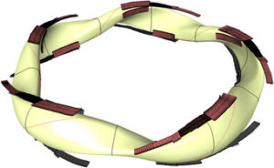
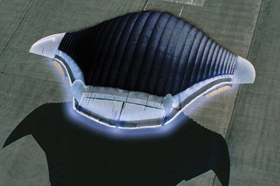
Wide angle view of the interior of the Wendelstein 7-X plasma vessel, showing the different armor materials designed to take up the heat from the plasma. The surface contour of the wall follows the shape of the plasma. On average, the radius of the plasma is 55 cm. Credit: Bernhard Ludewig, Max Planck Institute of Plasma Physics

At the end of 2018, operation of the W7-X ceased and a new round of modifications was started.  Key upgrades being implemented now for the W7-X are:

  • Installation of new water-cooled inner cladding on large sections of the plasma vessel to enable the W7-X to handle higher heating loads and longer plasma pulses, up to 30 minutes.
  • Installation of ten double strip, water-cooled divertor plates on the inner wall of the plasma vessel. Divertors are the parts of the new cladding system used to regulate the interaction between plasma and the inner wall of the plasma vessel.  Without water cooling, the heat-resistant divertor tiles made of carbon-fiber-reinforced carbon could not withstand the heat load for the intended 30-minute plasma pulses.

In ten curved double strips, the divertor plates (brown) follow the shape of the twisted plasma (yellow).  Source: IPP

IPP reports that this upgrade work is expected to continue until the end of 2021.  You’ll find more details on the upgrade work, including the design of the divertors, on the IPP website at the following link:  https://www.ipp.mpg.de/4828222/01_20

Conclusion

Following the success of two Wendelstein 7-X experimental campaigns from March 2016 to October 2018, a promising path forward is being pursued by the Max Planck Institute for Plasma Physics.  Nonetheless, I believe my previous conclusion (below, from the original post in 2017) still stands.  We’ll know a lot more after the W7-X upgrade work is completed and operations resume in late 2021.

So the jury is still out on the ability of advanced, optimized stellarators to take the lead over tokamaks in the long, hard journey toward the goal of delivering usable power from a fusion machine.  Hopefully, the advanced stellarators will move the fusion community closer to that goal.  No doubt, we still have a very long way to go before fusion power becomes a reality.

For more background information on stellarators:

A summary of Dr. Spitzer’s pioneering work at PPPL is documented in the following presentation:

There are good briefings on the basics of stellarator design and operation in the following two documents:

Preliminary Design of an Experimental World-Circling Spaceship

Peter Lobner

The title of this post also is the title of the first RAND report, SM-11827, which was issued on 5 May 1946 when Project RAND still was part of the Douglas Aircraft Company. The basic concept for an oxygen-alcohol fueled multi-stage world-circling spaceship is shown below.

Source: RAND

Source: RAND

Now, more than 70 years later, it’s very interesting to read this report to gain an appreciation of the state of the art of rocketry in the U.S. in 1946, which already was benefiting from German experience with the V-2 and other rocket programs during WW II.

RAND offers the following abstract for SM-11827:

“More than eleven years before the orbiting of Sputnik, history’s first artificial space satellite, Project RAND — then active within Douglas Aircraft Company’s Engineering Division — released its first report: Preliminary Design of an Experimental World-Circling Spaceship (SM-11827), May 2, 1946. Interest in the feasibility of space satellites had surfaced somewhat earlier in a Navy proposal for an interservice space program (March 1946). Major General Curtis E. LeMay, then Deputy Chief of the Air Staff for Research and Development, considered space operations to be an extension of air operations. He tasked Project RAND to undertake a feasibility study of its own with a three-week deadline. The resulting report arrived two days before a critical review of the subject with the Navy. The central argument turns on the feasibility of such a space vehicle from an engineering standpoint, but alongside the curves and tabulations are visionary statements, such as that by Louis Ridenour on the significance of satellites to man’s store of knowledge, and that of Francis Clauser on the possibility of man in space. But the most riveting observation, one that deserves an honored place in the Central Premonitions Registry, was made by one of the contributors, Jimmy Lipp (head of Project RAND’s Missile Division), in a follow-on paper nine months later: ‘Since mastery of the elements is a reliable index of material progress, the nation which first makes significant achievements in space travel will be acknowledged as the world leader in both military and scientific techniques. To visualize the impact on the world, one can imagine the consternation and admiration that would be felt here if the United States were to discover suddenly that some other nation had already put up a successful satellite.’”

You can buy the book from several on-line sellers or directly from RAND. However you also can download the complete report for free in three pdf files that you’ll find on the RAND website at the following link:

https://www.rand.org/pubs/special_memoranda/SM11827.html