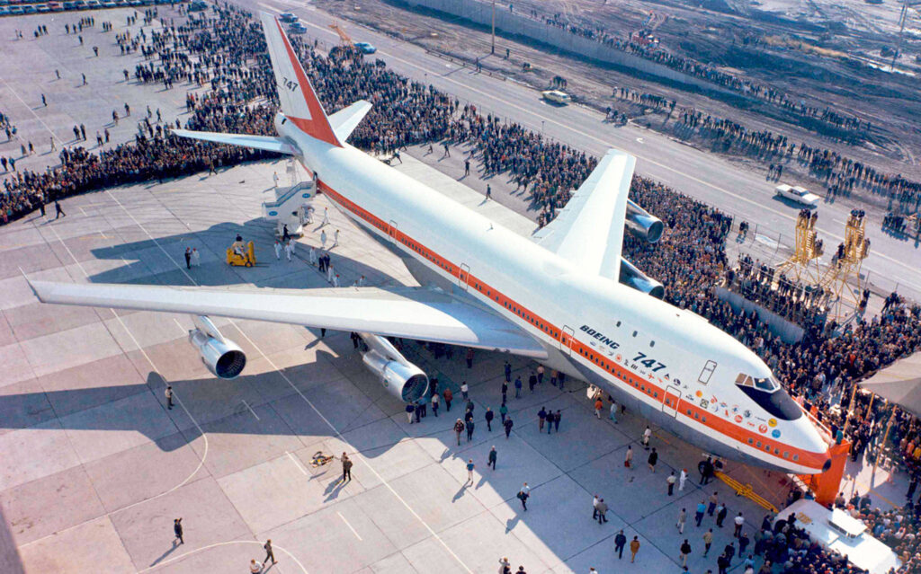
On 30 September 1968, the first Boeing 747 was rolled out at the company’s plant in Everett, WA. The first flight took place on 9 February 1969, and the FAA certified the 747 in December of that year. Pan Am was the first airline to offer Boeing 747 service on 22 January 1970, flying from New York to London.
1st Boeing 747 rolled out on 30 September 1968. Source: Everett Herald
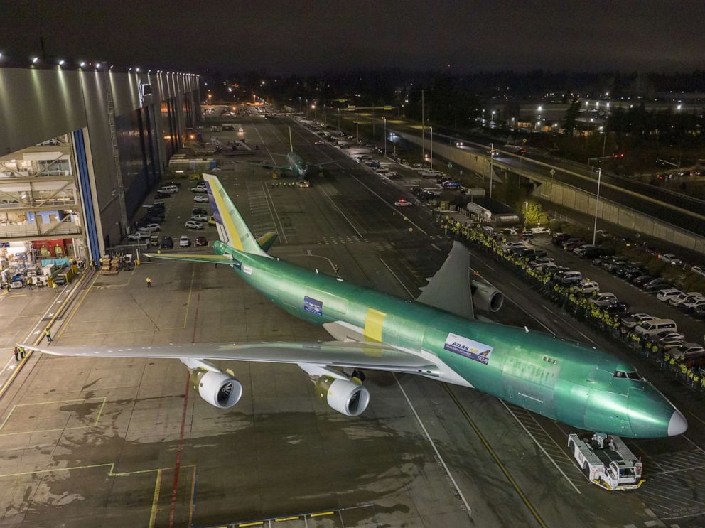
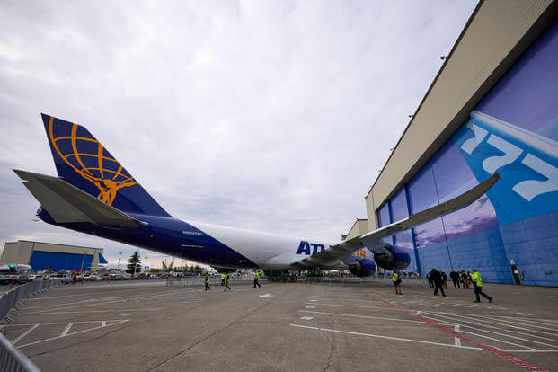
After a 54-year production run, the last 747, a 747-8 freighter, was rolled out of the factory on Tuesday, 6 December 2022. Boeing built a total of 1,574 747s in a range of models for commercial and military customers.
Boeing’s last 747 rolled off the assembly line. Source: Paul Weatherman/Boeing
In 2016 the Defense Science Board (DSB) identified energy as a critical enabler of future military operations. The DoD’s Strategic Capabilities Office (SCO) launched Project Pele with the objective to design, build, and demonstrate a prototype mobile nuclear reactor to provide reliable and resilient electric power, while minimizing risk of nuclear proliferation, environmental damage, or harm to nearby personnel or populations.
The Pele reactor will be the first electricity-generating Generation IV nuclear reactor built in the United States. Check out the DoD Office of the Under Secretary of Defense, Research and Engineering (OUSD(R&E)) website for the Project Pele Environmental Impact Statement (EIS) here: https://www.cto.mil/pele_eis/
The Pele reactor will use High-Assay, Low-Enriched Uranium (HALEU, <20% enriched) fuel in the form of TRstructural ISOtropic (TRISO) coated fuel pellets (each about the size of a poppy seed).
Cross-section of a TRISO particle, greatly magnified. Source: DOE
The reactor will be assembled and initially operated at the Idaho National Laboratory (INL), under the safety oversight of the Department of Energy (DOE). The Pele reactor is expected to be transportable by rail, truck or cargo aircraft.
Pele reactor modes of transportation. Source: GAO
There’s a good status update on Project Pele in a February 2023 article on the Energy Intelligence website, “Interview: Pentagon’s Jeff Waksman on Project Pele Microreactor,” at the following link: https://www.energyintel.com/00000186-7b02-d1cb-a3ee-ffbf32940000
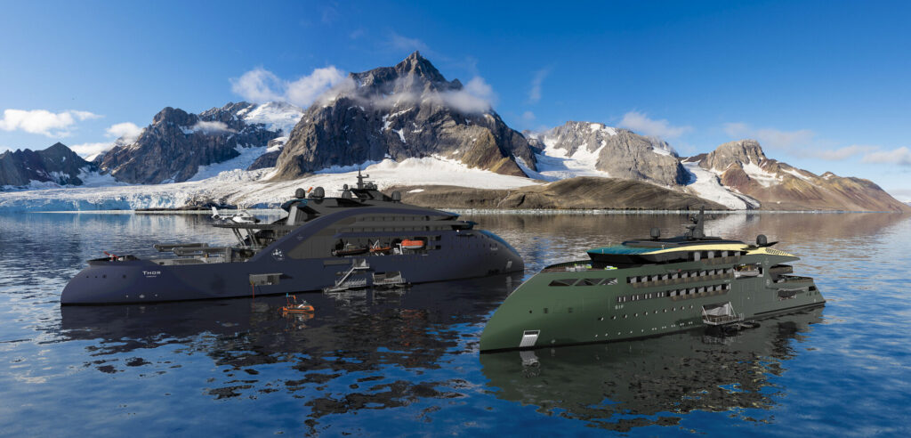
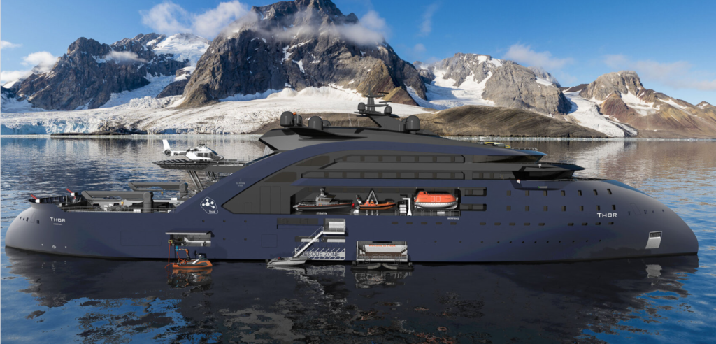
In June 2022, the Norwegian firm Ulstein (https://ulstein.com) announced their conceptual design of a Replenishment, Research and Rescue (3R) vessel named Thor that will be powered by a thorium molten salt reactor (MSR). This vessel can function as a seaborne mobile charging station for a small fleet of electrically-powered expedition / cruise ships that are designed to operate in environmentally sensitive areas such as the Arctic and Antarctic. Other environmentally sensitive areas include the West Norwegian Fjords, which are UNESCO World Heritage sites that will be closed in 2026 to all ships that are not zero-emission. In the future, similar regulations could be in place to protect other environmentally sensitive regions of the world, thereby reinforcing Ulstein’s business case behind Thor and its all-electric companion vessels.
Thor is a 149-meter (500-foot) long, zero-emission, nuclear-powered vessel that features Ulstein’s striking, backwards-sloping X-bow, which is claimed to result in a smoother ride, higher speed while using less energy, and less mechanical wear than a ship with a conventional bow.
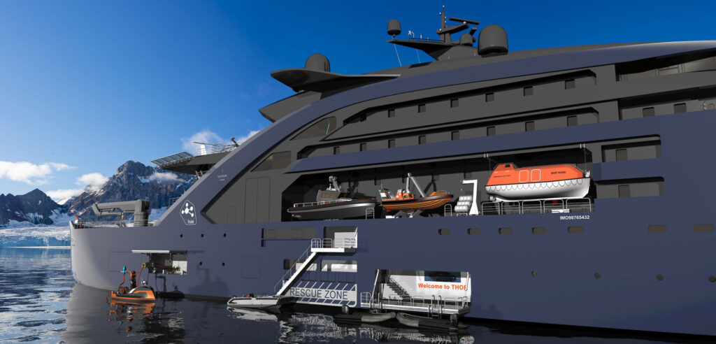
For its R3 mission, Thor would be outfitted with work boats, cranes, a helicopter landing pad, unmanned aerial vehicles (UAVs), unmanned surface vessels, firefighting equipment, rescue booms, a lecture hall and laboratories.
As a charging station, Thor would be sized to recharge four all-electric vessels simultaneously.
Thor. Source: Ulstein
Thor also could serve as a floating power station, replacing diesel power barges in some developing countries or in some disaster areas while the local electric power infrastructure is being repaired.
Ulstein projects that an operational Thor vessel could be launched in “10 to 15 years.” However, the development and licensing of a marine MSR is on the critical path for that schedule.
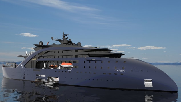
Thor, starboard side views. Source, both graphics: Ulstein
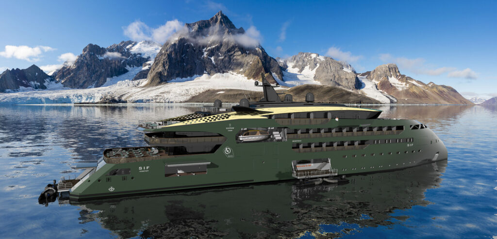
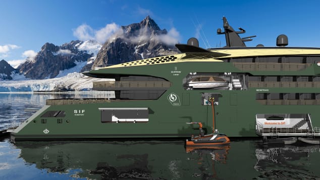
3. The all-electric Sif expedition / cruise ship
Sif, named after the goddess who was Thor’s wife, is a design concept for a 100-meter (330-foot) long, all-electric, zero-emission expedition / cruise ship designed to operate with minimal impact in environmentally sensitive areas. The ship will be powered by a new generation of solid batteries that are expected to offer greater capacity and resistance to fire than lithium-ion batteries used commonly today. It will be periodically recharged at sea by Thor.
The ship can accommodate 80 passengers and 80 crew.
Sif, starboard side view. Source, both graphics: Ulstein
4. A marine MSR power plant
The pressurized water reactor (PWR) is the predominant marine nuclear power plant in use today, primarily in military vessels, but also in Russian icebreakers and a floating nuclear power plant in the Russian Arctic.
Ulstein reported that it has been exploring MSR technology because of its favorable operating and safety characteristics. For example, an MSR operates at atmospheric pressure (unlike a PWR) and passive features and systems maintain safety in an emergency. If the core overheats, the molten salt fuel/coolant mixture automatically drains out of the reactor and into a containment vessel where it safely solidifies and can be reused. You’ll find a good overview of MSR technology here: https://whatisnuclear.com/msr.html
While a few experimental MSRs have operated in the past, no MSR has been subject to a commercial nuclear licensing review, even for a land-based application. Ulstein favors a thorium-fueled MSR. The thorium-uranium-233 fuel cycle introduces additional technical and nuclear licensing uncertainties because of the lack of operational and nuclear regulatory precedents.
Several firms are developing MSR concepts. However, the combination of a marine MSR and a thorium fuel cycle remains elusive. Two uranium-fueled marine MSR design concepts are described below.
Seaborg Technologies
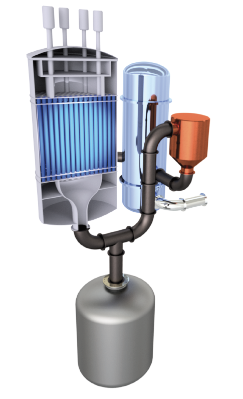
The Danish firm Seaborg Technologies (https://www.seaborg.com), founded in 2014, is developing a compact MSR (CMSR) with a rating of about 250 MWt / 100 MWe for use in power barges (floating nuclear power plants) of their own design (see my 16 May 2021 post). The thermal-spectrum CMSR uses uranium-235 fuel in a molten proprietary salt, with a separate sodium hydroxide (NaOH) moderator.
A Seaborg Technologies CMSR module could generate100 MWe. Dump tank shown below reactor. Source: Seaborg via NEI (2022)
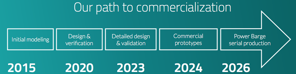
Seaborg’s development time line calls for a commercial CMSR prototype to be built in 2024, with commercial production of power barges beginning in 2026.
Source: Seaborg (2022)
In April 2022, Seaborg and the Korean shipbuilding firm Samsung Heavy Industries signed a partnership agreement for manufacturing and selling turnkey CMSR power barges.
On 10 June 2022, Seaborg was selected by the European Innovation Council to receive a significant (potentially up to €17.5 million) innovation grant to help accelerate their work on the CMSR.
CORE-POWER and the Southern Company consortium
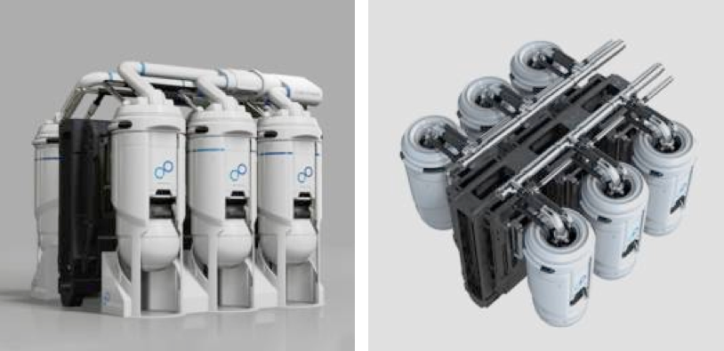
The UK firm CORE-POWER Ltd. (https://corepower.energy), founded in 2018, began with a concept for a compact uranium-235 fueled, molten chloride salt reactor named the m-MSR for marine applications. This modular, inherently safe, 15 MWe micro-reactor system was designed as a zero-carbon replacement power source for the fossil-fueled power plants in many existing commercial marine vessels. It also was intended for use as the original power source for new vessels, as proposed for the Earth 300 Eco-Yacht design concept unveiled by entrepreneur Aaron Olivera in April 2021 (see my 17 April 2021 post). The power output of a modular CORE-POWER m-MSR installation could be scaled to meet operational needs by adding reactor modules in compact arrangements suitable for shipboard installation.
A set of six small, compact CORE-POWER m-MSR modules could generate90 MWe. Dump tank not shown. Source: CORE-POWER
In November 2020, CORE-POWER announced that it had joined an international consortium to develop MSRs. This team includes the US nuclear utility company Southern Company (https://www.southerncompany.com), US small modular reactor developer TerraPower (https://www.terrapower.com) and nuclear technology company Orano USA (https://www.orano.group/usa/en). In the consortium, TerraPower is responsible for the fast-spectrum Molten Chloride Fast Reactor (MCFR). CORE-POWER is responsible for maritime readiness and regulatory approvals.
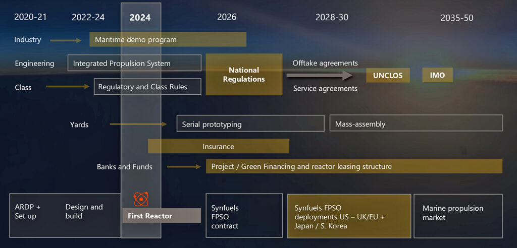
This consortium applied to the US Department of Energy (DOE) to participate in cost-share risk reduction awards under the Advanced Reactor Demonstration Program (ARDP), to develop a prototype MCFR as a proof-of-concept for a medium-scale commercial-grade reactor. In December 2020, the consortium was awarded $90.4 million, with the goal of demonstrating the first MCFR in 2024. DOE reported, “They expect to begin testing in a $20 million integrated effects test facility starting in 2022. The team has successfully scaled up the salt manufacturing process to enable immediate testing. Data generated from the test facility will be used to validate thermal hydraulics and safety analysis codes for licensing of the reactor.”In February 2021, CORE-POWER presented the MCFR development schedule in the following chart, which shows the MCFR becoming available for deployment in marine propulsion in about 2035. This is within the 10 to 15 year timescale projected by Ulstein for their first Thor vessel.
Source: CORE-POWER (2021)
5. In conclusion
A seaborne nuclear-powered “charging station” supporting a small fleet of all-electric marine vessels provides a zero-carbon solution for operating in protected, environmentally sensitive areas that otherwise would be off limits to visitors. Ulstein’s concept for the MSR-powered Thor R3 vessel and the Sif companion vessel is a clever approach for implementing that strategy.
It appears that a uranium-fueled marine MSR could be commercially available in the 10 to 15 year time frame Ulstein projects for deploying Thor and Sif. The technical and nuclear regulatory uncertainties associated with a thorium-fueled marine MSR will require a considerably longer time frame.
“’Thor’ – a Thorium Molten Salt Reactor ship design by Ulstein for Replenishment, Research and Rescue,” (2:16 min), Ulstein, 26 April 2022: https://www.youtube.com/watch?v=IBRVb0-0kAw
The World Air League is the organizer for a monumental airship race around the globe that will be held between September 2023 and May 2024. The World Air League describes their mission as follows:
“The mission and vision of the World Air League are to promote the advancement of lighter-than-air aviation for a sustainable future. The World Air League is creating the World Sky Race as an epic challenge to inspire inventors to invent and adventurers to compete. For strategic impact and purpose, the World Air League in embedding the World Sky Race® to be included in the global educational system to provide the world’s next-generation with a path to explore with their destination an alternate greener, cleaner future.”
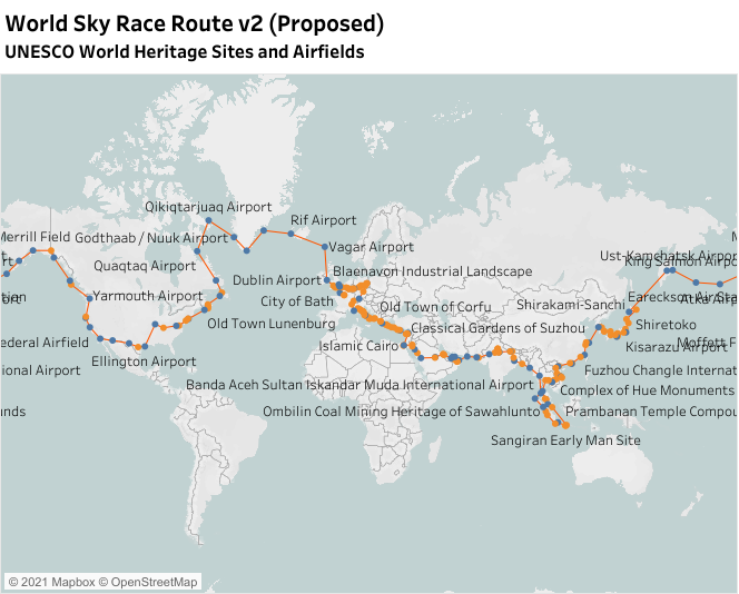
The upcoming World Sky Race® will launch in September 2023 when the competing airships cross the Prime Meridian heading east over Greenwich, London, and will end eight months later in Paris in May 2024, after the competitors have circumnavigated the globe. During the eight-month race, the airships will be flying over 130+ UNESCO World Heritage Sites and cities. Hopefully this flying caravan will inspire people worldwide to the green transportation opportunities represented by modern airships. The following map shows the proposed route.
Source: World Air League
The following travel poster images provide inspiring views of some of the destinations that will be visited during the upcoming World Sky Race®.
Source: World Air League
The World Air League previously attempted to organize the inaugural World Sky Race® in 2010. That race didn’t occur. Hopefully the planned 2023 – 2024 race will become a reality and will be a rousing success.
On a 2016 road trip to the Black Hills, I had long transit days each way on Interstate 90 through southern Minnesota and South Dakota. One thing I noticed was that many of the heavy tractor-trailers on this high speed route were modern, streamlined vehicles that used a variety of aerodynamic devices that appeared useful for reducing aerodynamic drag and fuel consumption.
These tractor-trailers are Class 8 heavy trucks with a gross vehicle weight (GVW) of greater than 33,000 pounds (14,969 kg). The maximum GVW is set on a case-by-case basis using the Federal Bridge Formula Weights published by the Department of Transportation’s (DOT) Federal Highway Administration (FHWA) at the following link: https://ops.fhwa.dot.gov/freight/publications/brdg_frm_wghts/index.htm
For example, a long 5-axle tractor-trailer, commonly called an “18-wheeler,” can have a GVW up to 85,500 pounds (38,782 kg), but it is limited to a maximum GVW of 80,000 pounds (36,287 kg) when operating on federal interstate highways. The higher weight limit may apply on other roads if permitted by state and local jurisdictions.
Class 8 Trucks make up only 4% of the vehicles on the road. However, they use about 20% of the nation’s transportation fuel. The following Department of Energy (DOE) video, entitled “Energy 101: Heavy Duty Vehicle Efficiency,” provides an introduction to what’s being done to introduce a variety of new technologies that will improve the performance and economy of Class 8 tractor-trailers while reducing their environmental impact: https://www.energy.gov/eere/videos/energy-101-heavy-duty-vehicle-efficiency
In this post, we’ll take a look at the following:
Three US and Canadian programs to improve tractor-trailer aerodynamics, fuel efficiency and freight efficiency:
US Environmental Protection Agency (EPA) SmartWay® Transport Partnership
Canadian Center for Surface Transportation Technology
US Department of Energy (DOE) SuperTruck program
The North American Council for Freight Efficiency’s (NACFE) Annual Fleet Fuel Study for 2019, which provides insights into the current state of the US Class 8 tractor-trailer fleet.
Accessories available to improve the aerodynamic efficiency of existing Class 8 tractor-trailers.
Aerodynamic Class 8 tractor-trailers from major US manufacturers, including:
Manufacturer’s flagship Class 8 trucks
Test trucks developed for the DOE SuperTruck program
Other advanced Class 8 truck designs and test trucks that are demonstrating new freight vehicle technologies.
Electric-powered Class 8 trucks that are about to enter service with the potential to revolutionize the freight trucking industry.
In the body of this post are links to 12 individual articles I’ve written on advanced Class 8 trucks, each of which can be downloaded as a pdf file. You’ll also find many other links to useful external resources.
2. US and Canadian programs to improve tractor-trailer aerodynamics and freight efficiency
Freight transportation is a cornerstone of the U.S. economy. In 2012, U.S. businesses spent $1 trillion to move $12 trillion worth of goods (8.5% of GDP). However, freight accounts for 9% of all U.S. greenhouse gas (GHG) emissions, and trucking is the dominant mode. The following programs are focused on reducing the GHG emissions of the freight trucking industry.
2.1 US SmartWay® Transport Partnership
The trucking industry’s ongoing efforts to improve heavy freight vehicle performance and economics were aided in 2004 by the creation of the SmartWay® Transport Partnership, which is administered by the Environmental Protection Agency (EPA). SmartWay® is a voluntarily program for achieving improved fuel efficiency and reducing the environmental impacts from freight transport. The goal is, “to move more freight, more miles, with lower emissions and less energy.” The SmartWay® website is at the following link: https://www.epa.gov/smartway
SmartWay® is promoting the following strategies to help the heavy trucking industry meet this goal:
Idle reduction
Speed control
Driver training
Aerodynamics
Tire technologies
Lubricants
Hybrid power trains
Improved freight logistics
Vehicle weight reduction
Intermodal freight capability
Alternative fuels
Long combination vehicles (LVCs, such as double trailers)
A truck and trailer fitted out with all the essential efficiency features can be sold as a SmartWay® “designated” model. A “designated” tractor-trailer combo can be as much as 20% more fuel-efficient than the comparable standard model.
2.2 Canadian Center for Surface Transportation Technology
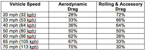
In May 2012, the Canadian Center for Surface Transportation Technology (CSTT) issued technical report CSTT-HVC-TR-205, entitled, “Review of Aerodynamic Drag Reduction Devices for Heavy Trucks and Buses.” In Table 2 of this report, CSTT provides the following table showing the relative power consumption of aerodynamic drag and rolling / accessory drag as a function of vehicle speed for a representative heavy truck on a zero grade road with properly inflated tires. Results will be different for streamlined trucks that have already have taken steps to reduce aero drag.
Relative magnitude of drag components. Source: CSTT, 2012
In this example, rolling / accessory drag dominates at lower speeds typical of urban driving. At 50 mph (80 kph) aerodynamic drag and rolling / accessory drag are approximately equal. At higher speeds, aerodynamic drag dominates power consumption. The speed limit on I-90 in South Dakota typically is 80 mph (129 kph). At this speed the aero drag contribution is even higher than shown in the above table.
Key points from this CSTT report include the following:
For tractor-trailers, pressure drag is the dominant component of vehicle drag, due primarily to the large surface area facing the main flow direction and the large, low-pressure wake resulting from the bluntness of the back end of the vehicle.
Aero-tractor models can reduce pressure drag by about 30% over the boxy classic style tractor.
Friction drag occurring along the sides and top of tractor-trailers makes only a small contribution to total drag (10% or less), so these areas are not strong candidates for drag-reduction.
The gap between the tractor and the trailer has a significant effect on total drag, particularly if the gap is large. Eliminating the gap entirely could reduce total drag by about 7%.
Side skirts or underbody boxes prevent airflow from entering the under-trailer region. These types of aero devices could reduce drag by 10 – 15%.
Wind-tunnel and road tests have demonstrated that a “boat tail” with a length of 24 – 32 inches (61 – 81 cm) is optimal for reducing drag due to the turbulent low-pressure region behind the trailer.
Adding a second trailer to form a long combination vehicle (LCV), and thus doubling the freight volumetric capacity, results in a very modest increase in drag coefficient (as low as about 10%) when compared to a single trailer vehicle.
In cold Canadian climates, the aerodynamic drag in winter can be nearly 20% greater than at standard conditions, due to the ambient air density. For highway tractor-trailers, this results in about a 10% increase in fuel consumption from aerodynamic drag when compared to the reference temperature, further emphasizing the importance of aerodynamic drag reduction strategies for the Canadian climate.
SuperTruck is major DOE technology innovation program with many industry partners representing a broad segment of the US industrial base for heavy tractor-trailers. This program, run by DOE’s Vehicle Technologies Office, focused on Class 8 trucks with internal combustion engines during the first two five-year program phases known as SuperTruck 1 and 2. Program focus shifted to electric powertrains in the third five-year phase known as SuperTruck 3.
Following is an overview of the SuperTruck program. Additional sources of information are listed at the end of this post.
SuperTruck 1 (2010-2016)
The first phase, known as SuperTruck 1, was a $284 million public-private partnership in which industry matched federal grants dollar-for-dollar. Four Class 8 truck manufacturers led teams in the SuperTruck 1 program:
Freightliner (Daimler North America)
International (Navistar)
Peterbilt (teamed with Cummins)
Volvo North America
DOE SuperTruck 1 teams. Source: DOE
Objectives for the DOE SuperTruck 1 program were:
Demonstrate a 50% freight efficiency improvement from a “baseline” 2009 model year Class 8 tractor-trailer.
Freight efficiency is the product of payload weight (in tons) and fuel economy (in miles per gallon), with results reported in North America as ton-miles per gallon.
Performance would be measured with a demonstration SuperTruck operated at 65,000 pounds GVW.
Average fuel efficiency of the baseline tractors in SuperTruck 1 was 6.2 mpg.
Improve engine efficiency by 8% to achieve 50% brake thermal efficiency (BTE), and thereby boost fuel efficiency by 16%.
The BTE of an engine is the ratio of Brake Power (BP) to Fuel Power (FP).
Brake power (BP) is the amount of power available at the crankshaft, taking into account engine friction losses (i.e., between cylinder and walls, crankshaft bearing, etc.).
Fuel power (FP) is a measure of the calorific value of the fuel used to deliver a particular value of BP.
Typical Class 8 truck diesel engines operate at 41 – 43% BTE. This means that 41 – 43% of the calorific value of the fuel is converted into power available at the crankshaft. The remaining 57 – 59% of the calorific value of the fuel is lost as heat that is carried off by the engine cooling system and engine exhaust system. In some advanced engines, turbochargers and waste heat recovery systems are used to increase BTE by recovering some energy from exhaust gases.
Show pathways for a further 5% improvement in engine efficiency (to achieve a BTE of 55%).
The four SuperTrucks developed by the respective teams are described in Section 5. All teams met or exceeded the SuperTruck I objectives set by DOE.
SuperTruck 2 (2017 – 2022)
SuperTruck 2 is a five-year, $160-million public-private partnership with industry matching federal grants dollar-for-dollar. Five teams are participating in the SuperTruck 2 program:
In August 2016, DOE announced that the four teams from SuperTruck 1 would continue their participation in SuperTruck 2.
A new team led by PACCAR, with truck manufacturer Kenworth as a team member, joined SuperTruck 2 in October 2017.
Objectives for the DOE SuperTruck 2 program are:
Improve freight efficiency (ton-miles per gallon) by 100% relative to a “best in class” 2009 truck (same baseline as in SuperTruck I), with a stretch goal of 120%.
Demonstrate 55% Brake Thermal Efficiency on an engine dynamometer.
Develop technologies that are commercially cost effective in terms of a simple payback.
Michael Berube, head of DOE’s Vehicle Technologies Office, acknowledged that the SuperTruck 2 objectives are beyond what the participants think they can achieve. However, with industry receiving dollar-for-dollar federal grants, Berube said, “…the program will allow them to try higher-risk technologies than they might on their own.”
Among the candidate technologies for SuperTruck 2 are:
Engines with waste heat recovery
Various forms of hybrid diesel-electric systems
More radical aerodynamic improvements, including active devices and completely redesigned cabs.
“Think of the benefit to the industry and to the country if they can meet that goal of doubling freight efficiency. There are 1.7 (to 2.5) million Class 8 trucks out there, each traveling an average of 66,000 miles a year. Doubling their efficiency could reduce petroleum consumption by 300 million barrels a year,” Berube said. At today’s fuel costs, that would save operators up to $20,000 per truck per year.
While most SuperTruck 2 programs wrapped up in 2022, PACCAR’s program was completed at the end of 2023 due to its later starting date.
SuperTruck 3 (2022 – 2027)
In October 2021, DOE launched a $199 million, five-year program to support the development of zero-emission vehicles, with $127 million directed to the SuperTruck 3 program, which will fund 50:50 cost-sharing projects to develop battery-electric and fuel cell medium- and heavy-duty trucks and freight system solutions with payload capacity and range equivalent to typical diesel-powered counterpart vehicles.
This DOE program includes three firms from the previous SuperTruck 2 program: PACCAR Inc., Volvo Group North America and Daimler Trucks North America.
PACCAR Inc.: $33 million in DOE cost-sharing funds to develop 18 Class 8 battery-electric vehicles with advanced batteries and a demonstration megawatt-class charging station.
Volvo Group North America: $18 million in DOE cost-sharing funds to develop a 400-mile-range Class 8 battery-electric tractor-trailer with advanced aerodynamics, electric braking, EV-optimized tires, automation and route planning. It also will develop and demonstrate a megawatt-class charging station.
Daimler Trucks North America: $26 million in DOE cost-sharing funds to develop and demonstrate two Class 8 hydrogen fuel cell trucks with a 600-mile range and 25,000-hour durability.
In addition, the SuperTruck 3 program includes Ford Motor Company and General Motors, both of which will focus on smaller freight vehicles, up to Class 6 Super Duty trucks.
3. The NACFE Annual Fleet Fuel Study
The North American Council for Freight Efficiency (NACFE) (https://nacfe.org/) describes its mission as working to “drive the development and adoption of efficiency enhancing, environmentally beneficial, and cost-effective technologies, services and methodologies in the North American freight industry.”
One of NACFE’s important products is the Annual Fleet Fuel Study, which reports on the adoption of 85 technologies and practices for improving freight efficiency among major North American Class 8 truck fleets operators. The 2019 Annual Fleet Fuel Study was based on data from 21 fleets operating 73,844 tractors and 239,292 trailers. You can download the NACFE 2019 Annual Fleet Fuel Survey here: https://nacfe.org/annual-fleet-fuel-studies/
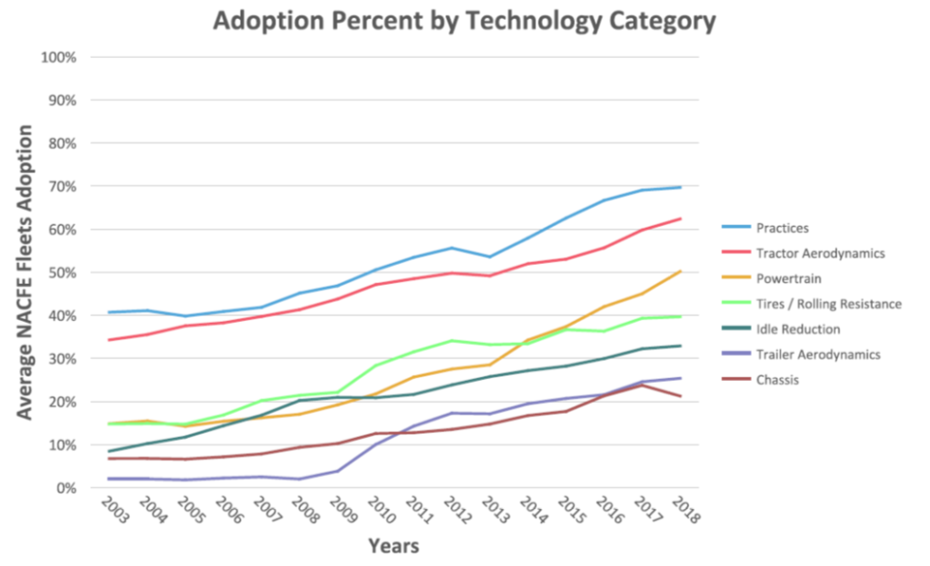
The following chart shows adoption rates among NACFE member fleets in seven technology categories. Tractor aerodynamic improvements (light blue line) have a high rate of adoption, at about 62% in 2018. In contrast, trailer aerodynamic improvements (purple line) have a much lower rate of adoption, at about 25% in 2018.
Source: NACFE 2019 Annual Fleet Fuel Study
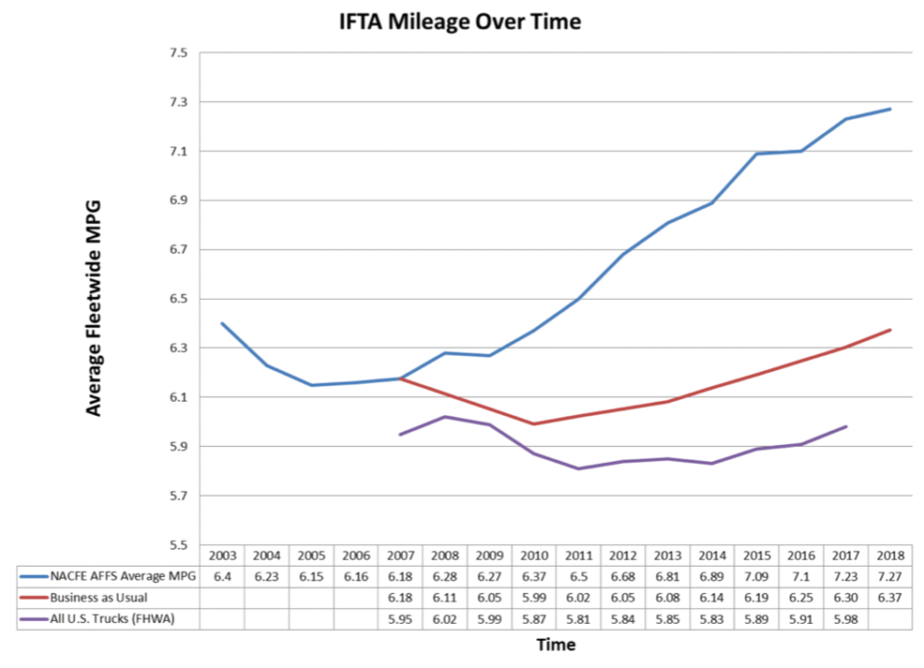
The Annual Fleet Fuel Study includes an analysis of the average fuel economy delivered by the combined Class 8 tractor-trailer fleet. Over the 16 years of this study, the average year-on-year improvement in fuel economy has been 2.0%. Fuel economy results are summarized in the following chart.
Source: NACFE 2019 Annual Fleet Fuel Study
Key points in this chart are:
The blue line represents the average fuel economy of the NACFE fleet from 2003 to 2018. In 2018, the NACFE fleet-wide average fuel economy increased to 7.27 mpg.
The red line is a hypothetical “business as usual” case, which is an estimate of what NACFE fleet fuel economy would be based only on improvements in engine efficiency. In 2018, “business as usual” would have yielded 6.37 mpg.
The difference between the blue and red curves represents the fuel efficiency improvements attributable to all other technologies and practices. In 2018, that difference was 0.9 mpg, meaning that actual performance was 14% better than the “business as usual” case.
The lowest (purple) curve is based on actual data reported to the U.S. Department of Transportation’s Federal Highway Administration (FHWA) for the approximately 2.5 million over-the-road tractor-trailers operating in the US. This average fleet fuel efficiency in 2017 was 5.98 mpg, well behind the fuel efficiency performance reported by NACFE fleet operators (which is included in the FHWA data).
4. Accessories available to improve the aerodynamic efficiency of existing tractor-trailers
The typical big rig has an aerodynamic drag coefficient, CD, of over 0.6, which has a huge effect on fuel economy, particularly during high-speed highway driving. Many truck manufacturers and third-party firms offer add-on kits with a variety of devices that can be installed on an existing tractor-trailer to improve its aerodynamic efficiency. Here we’ll look at a few of those devices:
Trailer tails (tapered boat-tails on the back of the trailer)
Trailer skirts
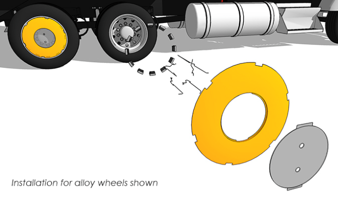
Aerodynamic wheel covers
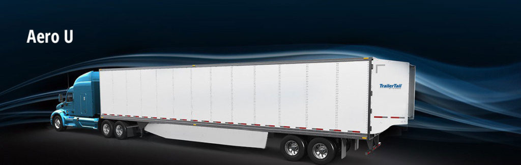
The U.S. firm STEMCO (http://www.stemco.com) offers two aero kits for improving conventional tractor-trailer aerodynamics:
TrailerTail®, which is installed at the back of the trailer, reduces the magnitude of the turbulent low-pressure area that forms behind the trailer at high speeds.
EcoSkirt®, which is installed under the trailer, reduces aerodynamic drag under the trailer where air hits the trailer’s rear axles. The side fairings streamline and guide the air around the sides and to the back of the trailer.
Both of these aerodynamic devices are shown in the following figure. This was a tractor-trailer configuration that I saw frequently on I-90.
Source: STEMCO
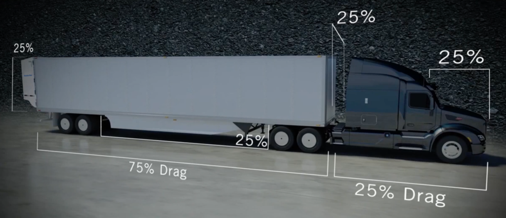
STEMCO allocates the primary sources of tractor-trailer aerodynamic drag as shown in the following figure.
Source: STEMCO
STEMCO claims the following benefits from their aero kits:
“TrailerTail® fuel savings complement other aerodynamic technologies.”
“A TrailerTail® reduces aerodynamic drag by over 12% equating to over 5% fuel efficiency improvement at 65 mph (105 kph) and over 12% fuel efficiency improvement when combined with STEMCO’s side skirts and other minor trailer modifications.”
STEMCO TrailerTail® meets the SmartWay® advanced trailer end fairings criteria for a minimum of 5% fuel savings and the STEMCO EcoSkirt® meets the advanced trailer skirts qualifications with greater than 5% fuel savings. The payback period for these aero devices is expected to be about one year.
You’ll find more details on STEMCO’s tractor-trailer drag reduction products, including a short “Aerodynamics 101” video, at the following link: http://www.stemco.com/aero-u/
More details on TrailerTail®, including its automatic deployment and operational use, are shown in a short video at the following link: https://www.youtube.com/watch?v=qPrM3-CCth8
Another firm, Aerotech Caps, offers a range of aero kits for improving truck aerodynamics, including aerodynamic wheel covers, aerodynamic trailer skirts, tail fairings and vortex generators. You can see their product line at the following link: https://aerotechcaps.com/#aerotechcaps
Source: Aerotech Caps
Aerotech Caps claims that its aerodynamic wheel covers deliver about 2.4% increased miles per gallon when installed on rear tractor and all trailer wheels. Payback period for this aero kit is expected to be about one year.
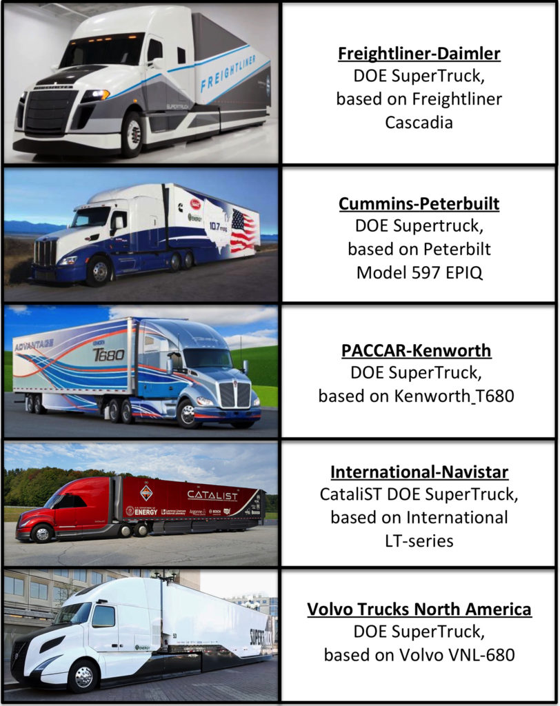
5. Aerodynamic Class 8 production tractor-trailers and SuperTrucks from major US manufacturers
Conventional, top-of-the-line tractor-trailers on the market today have significantly improved aerodynamic and fuel efficiency performance in comparison to their predecessors. The aero gains have been achieved by integrating many of the aero features described above into the basic designs for the latest Class 8 tractor-trailers on the market. In addition, optional aero kits are available to further improve performance.
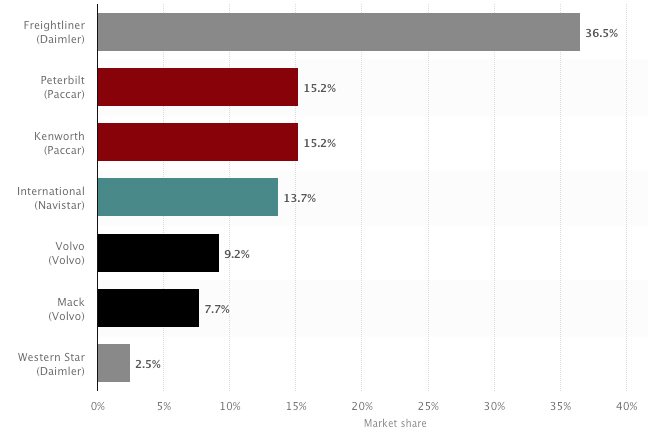
Class 8 truck manufacturers’ market share in the U.S. as of December 2019 is shown in the following chart.
Note that Freightliner is a Daimler North America brand along with Western Star. Peterbilt and Kenworth are PACCAR brands. International is a Navistar brand and Mack is a Volvo brand.
Now we’ll take a look at the most aerodynamic tractor-trailers offered in 2020 by the top five manufacturers in the US Class 8 truck market. Collectively, these manufacturers account for almost 90% of the US Class 8 heavy truck market.
Four of the five top manufacturers, Freightliner, Peterbilt, International and Volvo, led teams in the DOE SuperTruck 1 program (2010-2016) and are continuing their participation in the SuperTruck 2 program (2017 – 2022). Kenworth did not participate in SuperTruck 1, but did participate in SuperTruck 2 as a member of a new team led by their parent firm, PACCAR.
You’ll find my articles on these tractor-trailers at the following links:
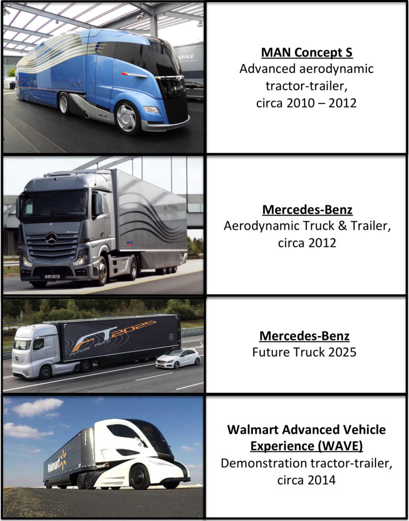
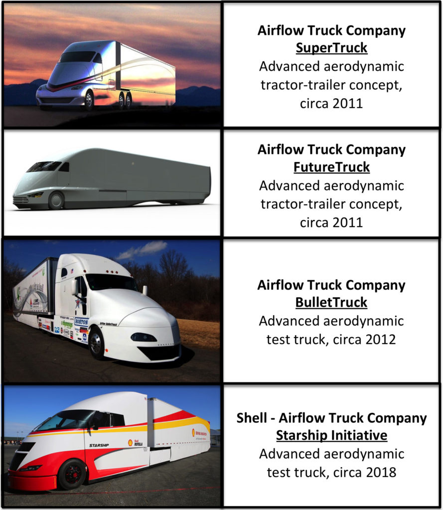
6. Other advanced Class 8 tractor-trailer designs and test trucks
The future of heavy freight vehicles is certain to include increasingly aerodynamic tractor-trailers with more efficient diesel and hybrid powertrains. While the five teams participating in the DOE SuperTruck program are demonstrating significantly improved Class 8 tractor-trailer performance, other firms have been working in parallel to develop their own advanced truck concepts and test trucks. In this section, we’ll take a look at the following advanced integrated tractor-trailers.
You’ll find my articles at these tractor-trailers at following links:
7. Advanced electric-powered Class 8 tractor-trailers
A variety of electric-powered heavy trucks and tractor trailers are being developed for the worldwide market and several are being operationally tested. The most common electric energy sources are be battery-electric or hydrogen fuel cell + battery.
“Battery electric vehicles are around 90% efficient with the electricity that flows into the charger when it is converted into motion by the onboard motors.”
“Hydrogen fuel cell vehicles are understandably less efficient, using the source electricity to break apart water, compress it, transfer it into the vehicle, and then convert the hydrogen back into electricity by combining it with ambient oxygen. Estimates for the efficiency of the electricity used to produce hydrogen, then get converted back to electricity in fuel cell vehicles, is around 40%.”
Lithium-ion batteries currently are the dominant type of battery used in electric vehicles. Boston Consulting Group reported that one particular type, the lithium nickel-manganese-cobalt (NMC) battery, has good overall performance, excels on specific energy, has the lowest self-heating rate, and is a preferred candidate for electric vehicles. For more information, see the 10 July 2019 Battery University article, “BU-205: Types of Lithium-ion Batteries,” at the following link: https://batteryuniversity.com/learn/article/types_of_lithium_ion
While less efficient in overall energy conversion, the hydrogen fuel cell weighs much less and can store much more energy than a comparably-sized, current-generation battery packaged for a heavy-duty truck application. For more information on hydrogen fuel cells, see the May 2017 University of California (UC) Davis presentation, “Fuel Cells and Hydrogen in Long-Haul Trucks,” at the following link: https://steps.ucdavis.edu/wp-content/uploads/2017/05/Andy-Burke-Hydrogen-Fuel-Cell-Trucks.pdf
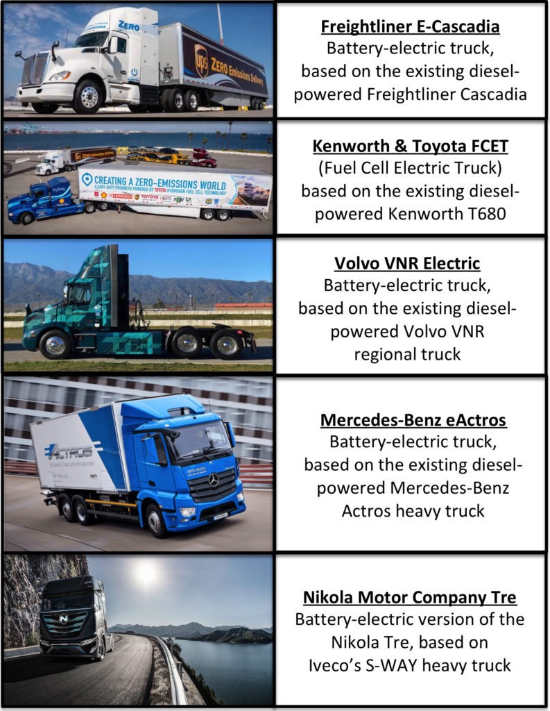
In 2020, several heavy-duty electric truck designs are adaptations of existing Class 8 tractor-trailers with all-new electric powertrains. Examples are shown in the following table.
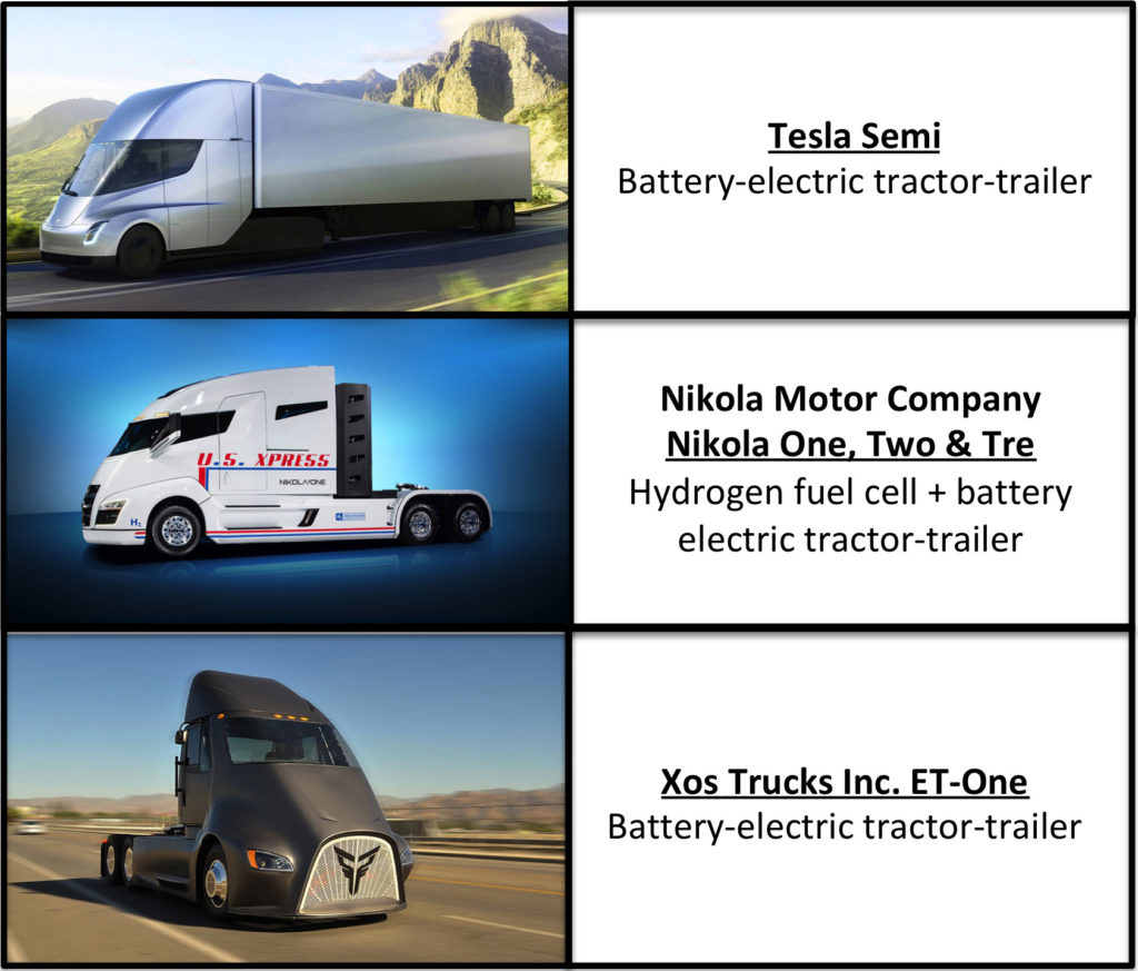
Some designs in 2020 were “clean-sheet” advanced electric-powered Class 8 tractor-trailers that also may offer a future path toward autonomous vehicle operation. Examples include:
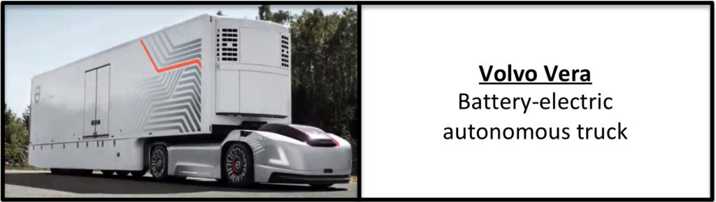
Then there are even more advanced electric-powered heavy trucks that are designed originally as autonomous freight haulers without provisions for a driver’s cab. For example:
You can get a good overview of the current state of electric-powered heavy truck development in the following October 2019 video by Automotive Territory: “10 All-Electric Trucks and Freighters Showcasing the Future of Cargo Vehicles” (11:17 minutes): https://www.youtube.com/watch?v=smAleMBEszs
In this section, we’ll take a look at the “clean-sheet” advanced electric-powered Class 8 tractor-trailers. You’ll find my articles at these tractor-trailers at following links:
The DOE-sponsored SuperTruck 3 program initiated in 2022, which is funding work to develop battery-electric and fuel cell medium- and heavy-duty trucks and freight system solutions, is not funding any of the above three companies.
8. Conclusions:
Freight currently accounts for 9% of all U.S. greenhouse gas (GHG) emissions, and trucking is the dominant mode. The gradual phase-in of tractor-trailers with refined aerodynamics and diesel engines is improving fleet-wide fuel economy and thereby helping to decrease the carbon footprint of long-haul trucking.
Large improvements in freight efficiency (the product of payload weight in tons and fuel economy in miles per gallon; ton-miles per gallon) were demonstrated during the DOE SuperTruck 1 program, and greater gains are expected in SuperTruck 2, which continued into 2023. In the meantime, truck manufacturers are implementing SuperTruck technologies in their production model tractor-trailers. This is a significant step in the right direction.
With the introduction of electric-powered tractor-trailers in the next decade, the trucking industry has an opportunity to revolutionize its operations by deploying fleets of zero-emission trucks. The very aerodynamic, electric-powered Tesla Semi and the smaller freight vehicles being developed by Xos seem to be good first steps in starting the electric freight revolution. They will be joined by other electric-powered tractor-trailers and smaller freight vehicles being developed under the DOE SuperTruck 3 program, which will run thru 2027.
For the electric-powered trucks to compete effectively with diesel and hybrid-powered truck, the truck manufacturers and the freight industry needs to support deployment of the diverse nation-wide infrastructures for very-high capacity battery recharging and hydrogen refueling. With these new infrastructures in place, electric-powered freight operations can become routine and make a big contribution to reducing GHG emissions and the environmental impact of the nation’s freight hauling industry.
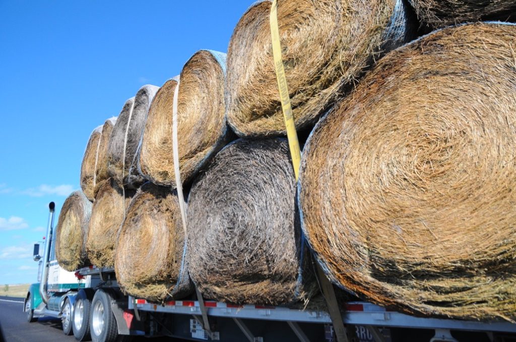
In spite of all of these opportunities for improving heavy tractor-trailer performance, there always will be cases when few of these are actually practical. As evidence, I offer the following photo taken at 80 mph on I-90 in South Dakota during my 2016 road trip. How do you optimize that giant drag coefficient?
National Academies report: “Review of the 21st Century Truck Partnership: Third Report,”, particularly Chapter 8, “SuperTruck,” 2015; https://www.nap.edu/download/21784
“NETL Project Partner Daimler Truck North America Debuts Next Level of Freight Efficiency with the Freightliner SuperTruck II,” National Energy Technology Laboratory press release, 3 August 2023: https://netl.doe.gov/node/12767
Modern Airships is a three-part document that contains an overview of modern airship and aerostat technology in Part 1 and links in Parts 1, 2 and 3 to more than 275 individual articles on historic and advanced airship designs. This is Part 1. Here are the links to the other two parts:
To help you navigate the large volume of material in these three documents, please refer to following indexes. The first index simply lists the article titles in alphabetic order within each Part.
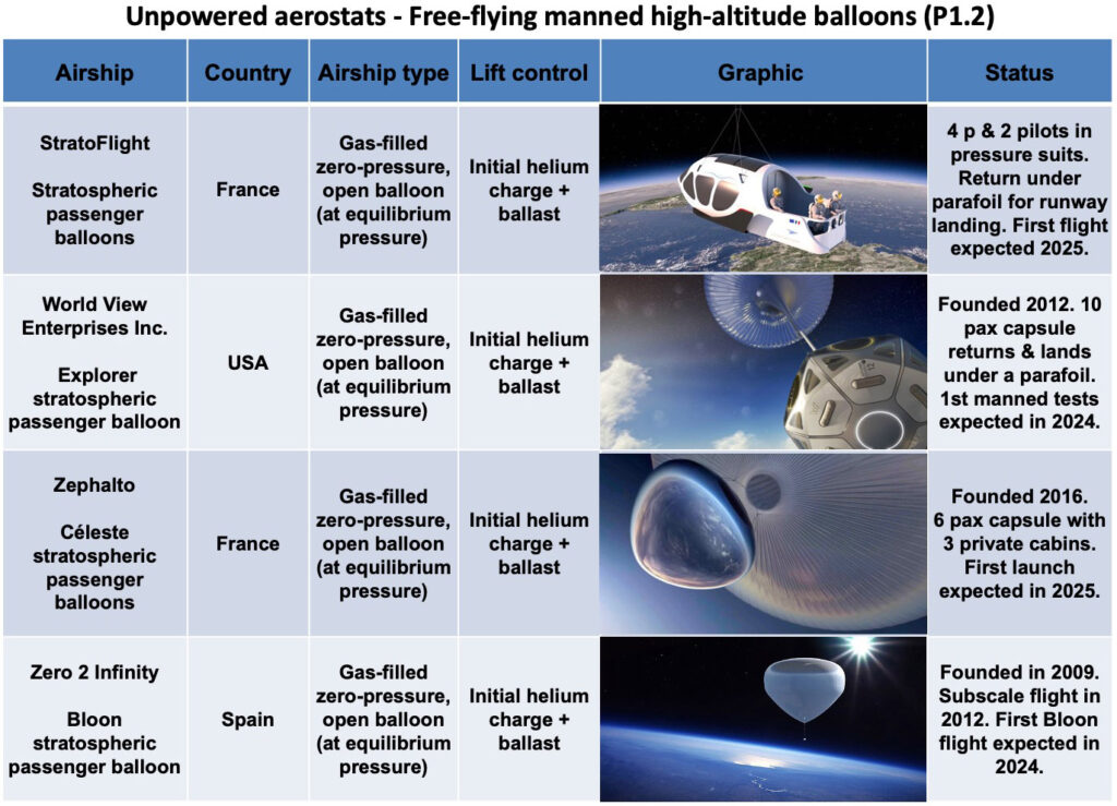
Parts 1 & 2 address similar types of airships and unpowered aerostats. The following airship type index enables you to see all of the airships and aerostats addressed in Parts 1 & 2, grouped by type, with direct links to the relevant articles.
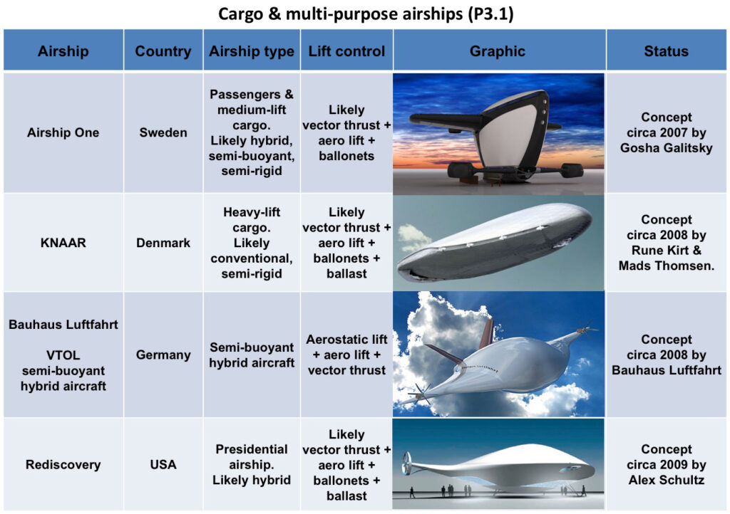
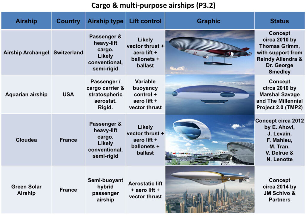
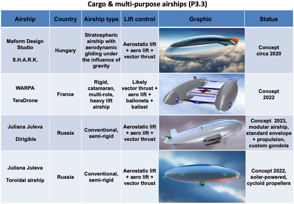
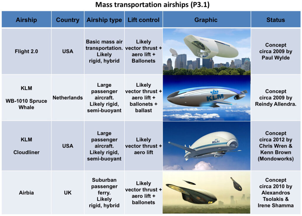
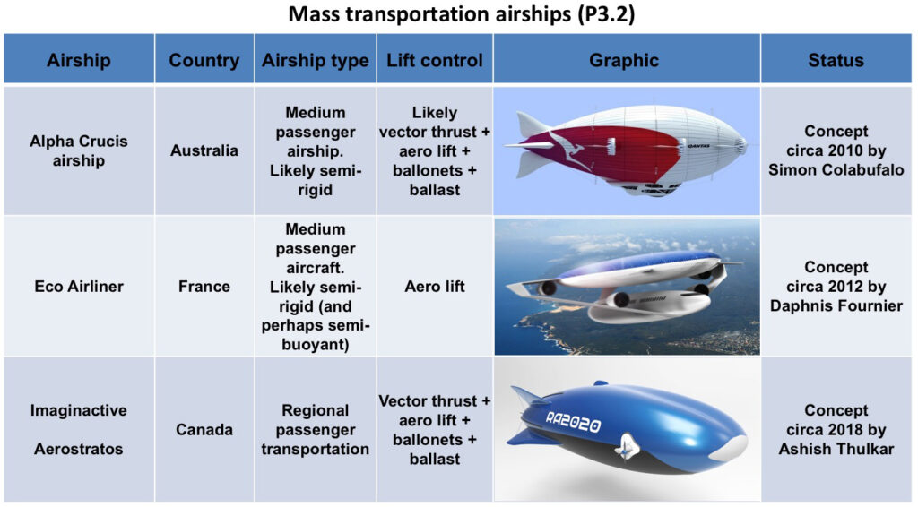
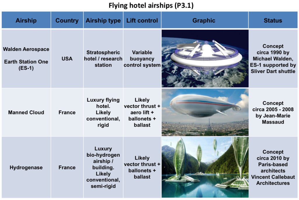
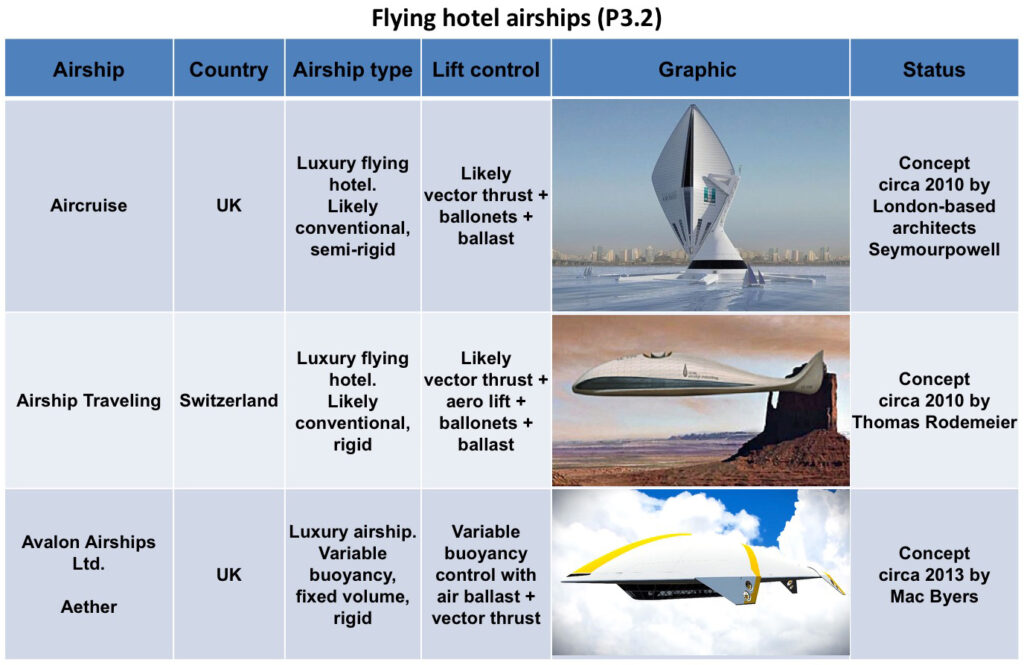
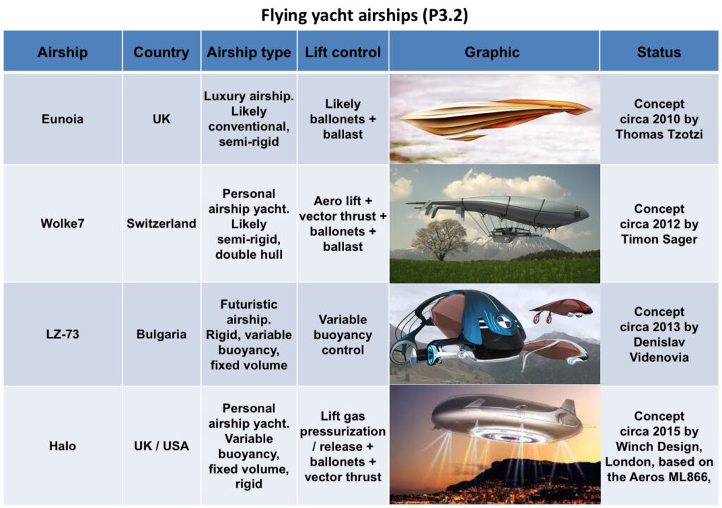
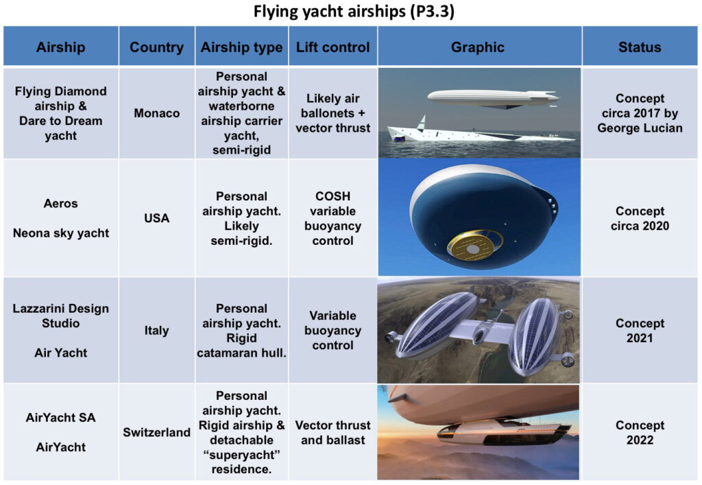
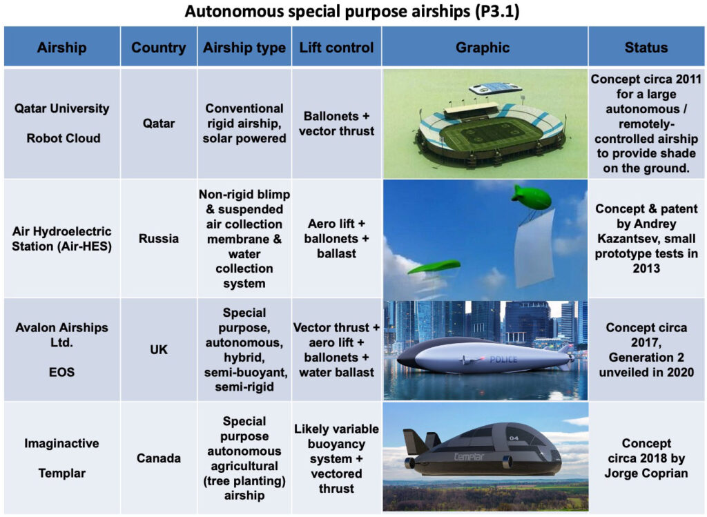
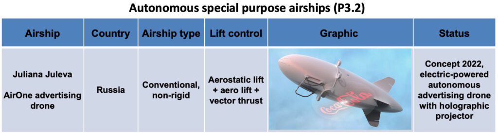
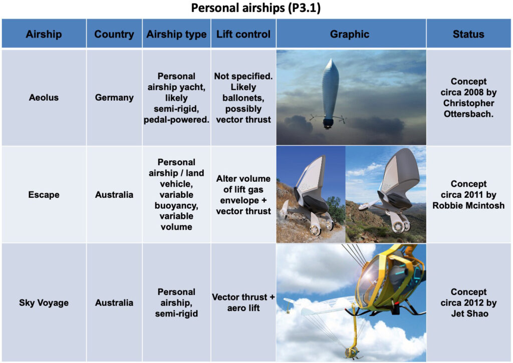
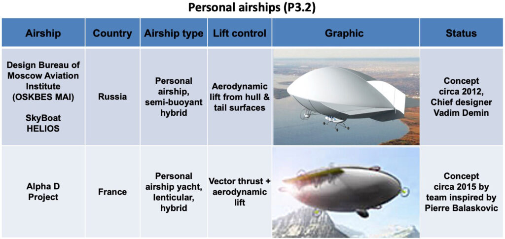
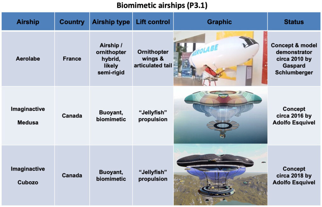
The airships described in Part 3 are relatively exotic concepts in comparison to the more utilitarian and heavy-lift airships that dominate Parts 1 and 2. As shown in the following index, the airships in Part 3 are organized by function rather than airship type, which sometimes is difficult to determine with the information available.
Modern Airships – Part 1 begins with an overview of modern airship and aerostat technology, continues with a graphic table that identifies the airships addressed in this part, and concludes by providing links to more than 100 individual articles on these airships. A downloadable pdf copy of Part 1 is available here:
If you have any comments or wish to identify errors in this document, please send me an e-mail to: [email protected].
I hope you’ll find the Modern Airships series to be informative, useful, and different from any other single document on this subject.
Best regards,
Peter Lobner
17 March 2024
Record of revisions to Part 1
Original Modern Airships post, 26 August 2016: addressed 14 airships in a single post.
Expanded the Modern Airships post and split it into three parts, 18 August 2019: Part 1 included 22 linked articles.
Part 1, Revision 1, 21 December 2020: Added 15 new articles, split the existing Aeros article into two articles and updated all of the original articles. Part 1 now had 38 articles.
Part 1, Revision 2, 3 April 2021: Updated the main text and 10 existing articles, and expanded and reorganized the graphic tables. Part 1 still had 38 articles
Part 1, Revision 3, 26 August 2021: Added 34 new articles, split the existing Helistat article into five articles and the Aereon article into two articles, and expanded and reorganized the graphic tables. Also updated 23 existing articles. Part 1 now had 77 articles.
Part 1, Revision 4, 12 February 2022: Added 12 new articles, split the existing Airlander article into two updated articles (prototype, production), moved Halo to Part 3, expanded the graphic tables and updated 17 additional existing articles. Part 1 now had 89 articles.
Part 1, Revision 5, 10 March 2022: Added 2 new articles, split rigid & semi-rigid airships in the graphic tables, and updated 58 existing articles. With this revision, all Part 1 linked articles have been updated in February or March 2022. Part 1 now has 91 articles.
Part 1, Revision 6, 17 March 2024: This revision includes a major reorganization of Parts 1 & 2 to better aggregate airships and unpowered aerostats by type, with a corresponding reorganization of the graphic tables. Over the past two years, 15 new articles were added to Part 1 and 28 articles were updated. In the final changes for Rev. 6, several articles were moved between Parts 1 & 2. Part 1 now has 107 articles.
Part 1, Rev. 6 incorporates the following changes since Rev. 5 was posted in March 2022
New articles:
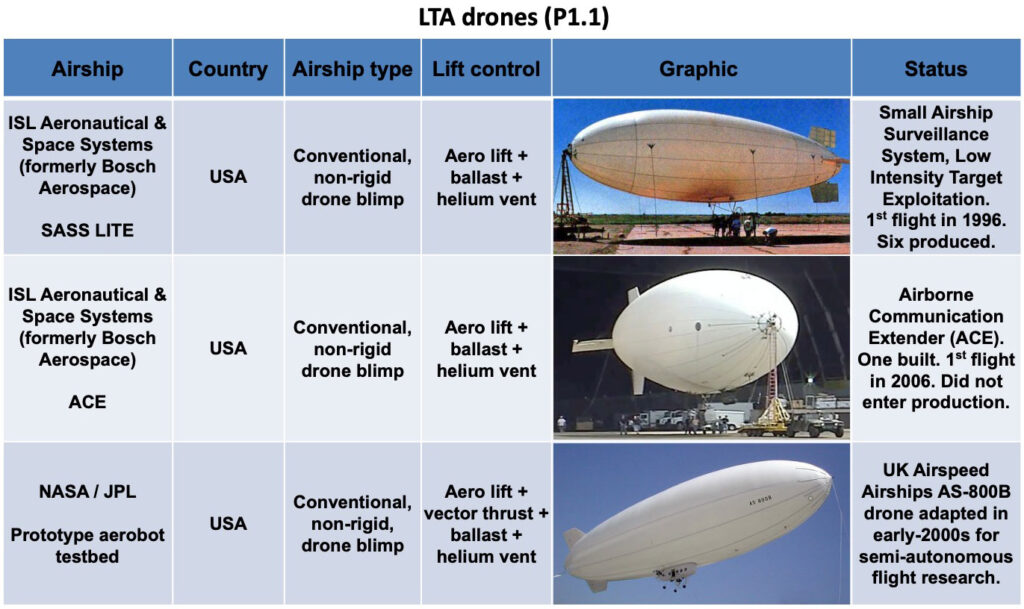
ISL Aeronautical & Space Systems (formerly Bosch Aerospace Inc.) – UAV blimps and tethered aerostats (12 June 2022)
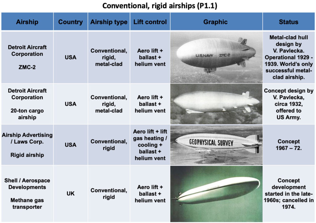
Detroit Aircraft Corporation – ZMC-2 metalclad airship (31 July 2022)
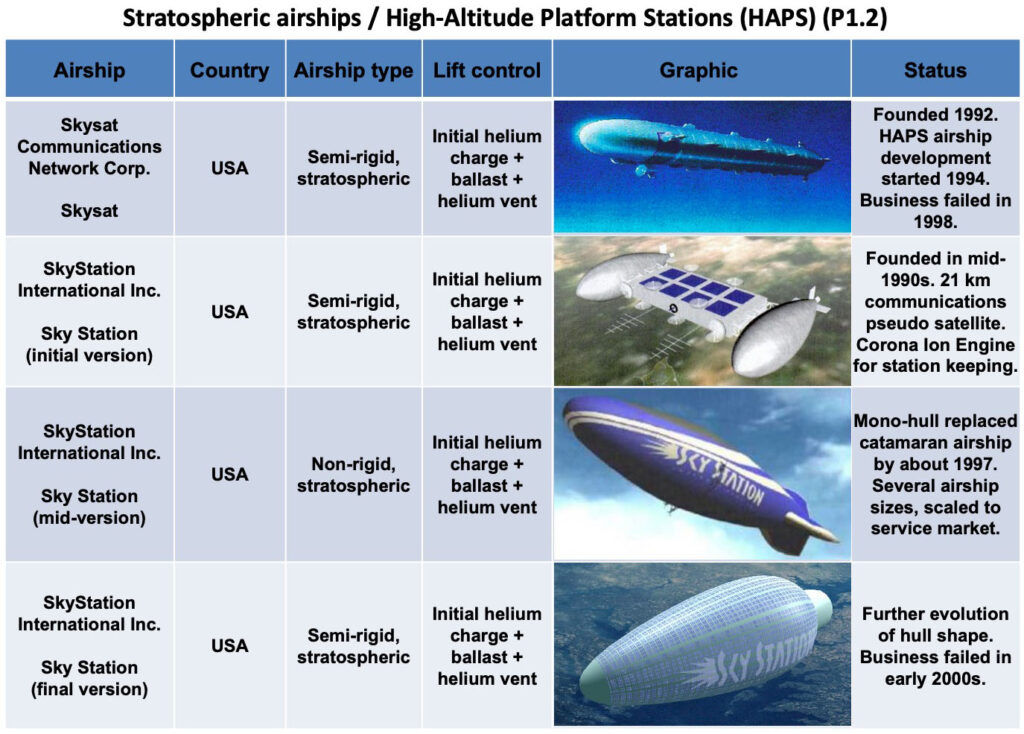
UPDATED AND MOVED FROM PART 2: Sky Station International (12 January 2024)
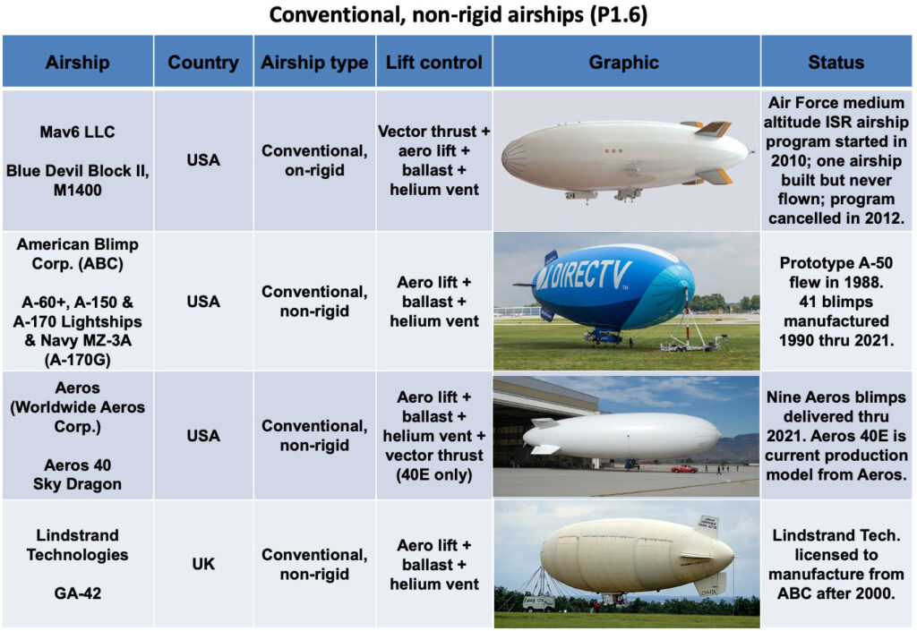
Mav6 LLC – Blue Devil Bock 2 – M1400 (6 February 2024)
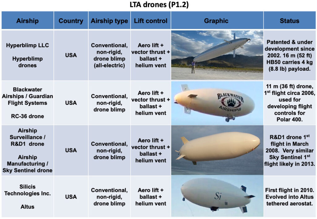
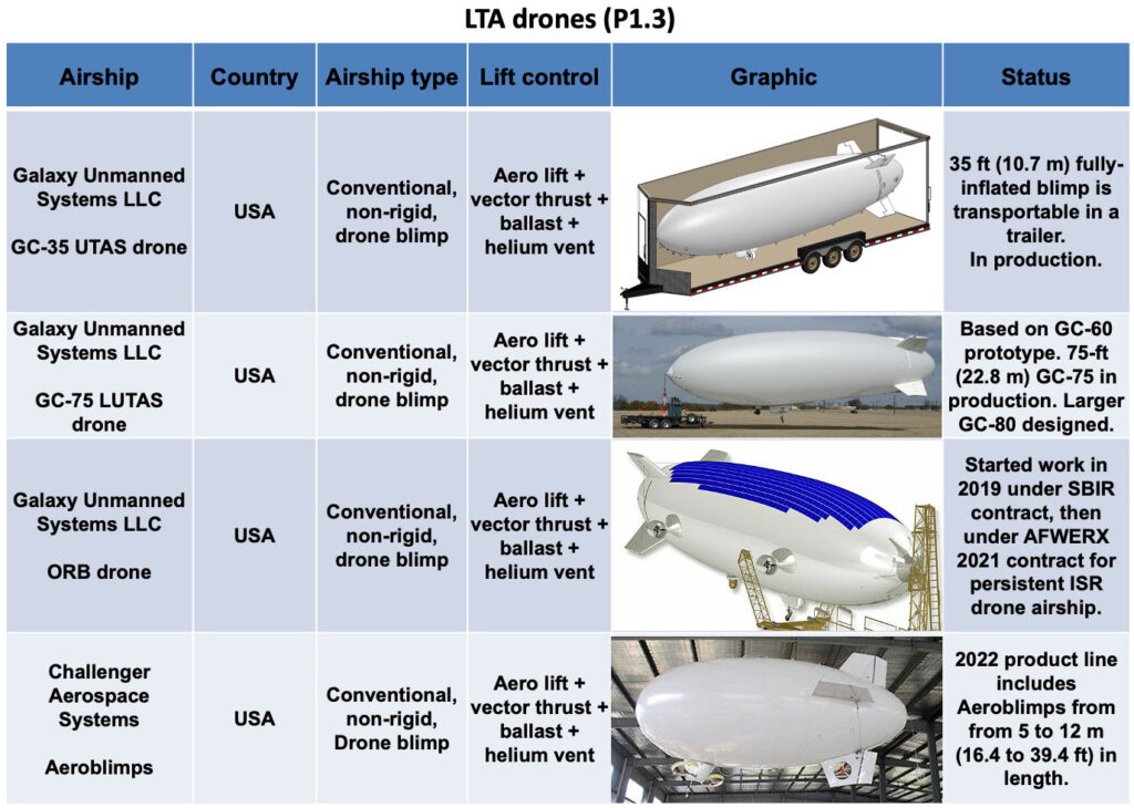
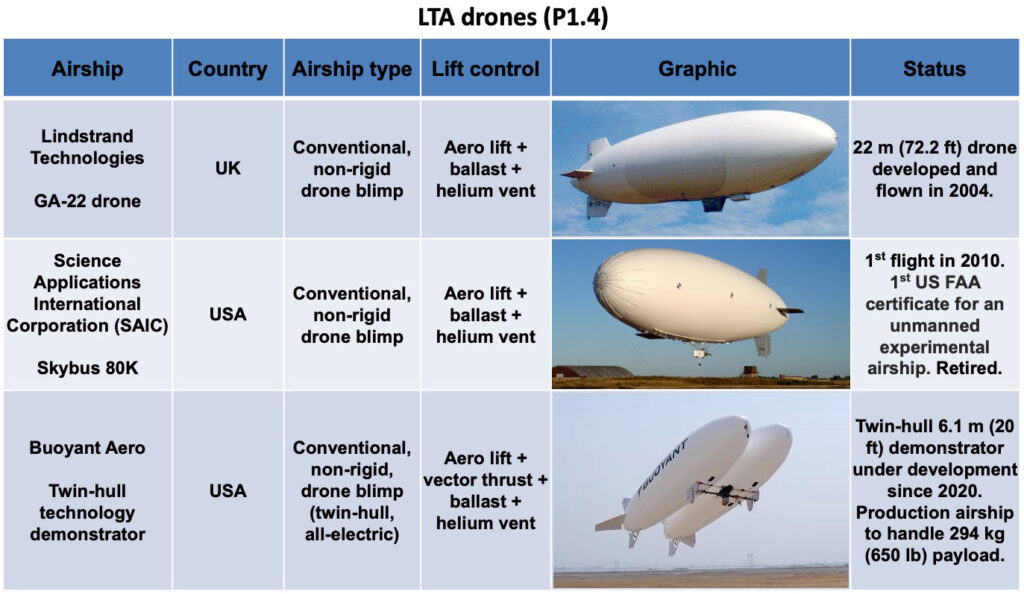
Major reorganization of the main text and update of the graphic table. Moved to Part 2: Airspeed, AURORA, Karma, AVIC AS700, Vantage, Tumencotrans BARS & Bella-1. Moved from Part 2: Aeros 40, Aeros G2R, Blackwater, Buoyant Aero, Challenger, Galaxy, Hyperblimp, Altaeros Energies aerostats (16 March 2024)
2. Well-established benefits and opportunities, but a risk-averse market
For several decades, there has been significant interest in the use of modern lighter-than-air craft and hybrid airships in a variety of military, commercial and other roles, including:
Heavy cargo carriers operating point-to-point between manufacturer and end-user, eliminating inter-modal load transfers enroute
Heavy cargo carriers serving remote and/or unimproved sites not adequately served by other modes of transportation
Disaster relief, particularly in areas not easily accessible by other means
Persistent optionally-manned surveillance platforms for military intelligence, surveillance & reconnaissance (ISR), maritime surveillance, border patrol, search and rescue
Passenger airships
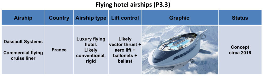
Commercial flying cruise liner / flying hotel
Airship yacht
Personal airship
Drone carrier
High altitude regional communications node
One of the very significant factors driving interest in modern airships is that they offer the potential to link isolated regions with the rest of the world while doing so in a way that should have lower environmental impacts than other transportation alternatives for those regions. This target market for airships exists in more than two-thirds of the world’s land area where more than half the world’s population live without direct access to paved roads and reliable ground transportation.
In spite of the significant interest and the development of many promising airship designs, an actual worldwide airship cargo and passenger transportation industry has been very slow in developing. To give you an example of how slow:
As of November 2023, other than a modest number of commercially certified blimps used largely as advertising platforms, the Zeppelin NT 07 is the only advanced airship that has been certified and is flying regularly in commercial passenger service.
At the March 2019 Aviation Innovations Conference – Cargo Airships in Toronto, Canada, Solar Ship CEO Jay Godsall proposed an industry-wide challenge to actually demonstrate by July 2021 airships that can move a 3 metric ton (6,614 lb) standard 20 foot intermodal container configured as a mobile medical lab 300 km (186 mi) to a remote location. Godsall noted that this capability would be of great value if it did exist, for example, in support of relief efforts in Africa and other regions of the world.
So in spite of the airship industry having developed many designs capable of transporting 10’s to 100’s of tons of cargo thousands of miles, today there is not a single airship than can transport a 3 metric ton (6,614 lb) payload 300 km (186 mi).
Why has the airship industry been so slow to develop? The bottom line has been a persistent lack of funding. With many manufacturers having invested in developing advanced designs in varying levels of detail, the first to secure adequate funding will be able to take the next steps to build and certify a manufacturing facility, build and flight test a full-scale prototype airship, complete the airship type certification process, and start offering a certified airship for sale.
There are some significant roadblocks in the way:
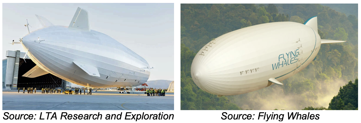
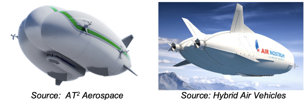
No full-scale prototypes are flying: Many airship firms currently have little more than slide presentations to show to potential investors and customers. There are few sub-scale airship demonstrators, but no full-scale prototypes. The airship firms are depending on potential investors and customers making a “leap of faith” that the “paper” airship actually can be delivered. However, this situation will change significantly in the next few years as several airship manufacturers (i.e., LTA Research and Exploration, Flying Whales and Hybrid Air Vehicles) finally complete their full-scale, large airship prototypes and commence flight testing.
Immature manufacturing capability: While the airship industry has been good at developing many advanced designs, some claiming to exist as “construction-ready” plans, few airship firms are in the process of building an airship factory. The industrial scale-up factor for an airship firm to go from the design and engineering facilities existing today to the facilities needed for series production of full-scale airships is huge. LTA Research and Exploration is one of the few firms with access to modernized large airship hangars (the former Goodyear Airdock in Akron OH and the former Navy airship hangars at Moffett Field, CA) for use as manufacturing facilities. In 2016, Russian airship manufacturer Augur RosAeroSystems proposed building a new factory to manufacture up to 10 ATLANT airships per year. The funding requirement for that factory was estimated at $157 million. The exact amount isn’t important. No matter how you look at it, it’s a big number. Large investments are needed for any airship firm to become a viable manufacturer.
Significant financial risk: The amount of funding needed by airship firms to make the next steps toward becoming a viable manufacturer exceeds the amount available from venture capitalists who are willing to accept significant risk. Private equity sources typically are risk averse. Public sources, or public-private partnerships, have been slow to develop an interest in the airship industry. The French airship firm Flying Whales appears to be the first to have gained access to significant funding from public institutions.
Significant regulatory risk: Current US, Canadian and European airship regulations were developed for non-rigid blimps and they fail to address how to certify most of the advanced airships currently under development. This means that the first airship manufacturers seeking type certificates for advanced airships will face uphill battles as they have to deal with aviation regulatory authorities struggling to fill in the big gaps in their regulatory framework and set precedents for later applicants. It is incumbent on the aviation regulatory authorities to get updated regulations in place in a timely manner and make the regulatory process predictable for existing and future applicants.
No airship operational infrastructure: There is nothing existing today that is intended to support the operation of new commercial airships tomorrow. The early airship operators will need to develop operating bases, hangar facilities, maintenance facilities, airship routes, and commercial arrangements for cargo and passengers. While many airship manufacturers boast that their designs can operate from unimproved sites without most or all of the traditional ground infrastructure required by zeppelins and blimps, the fact of the matter is that not all advanced airships will be operating from dirt fields and parked outside when not flying. There is real infrastructure to be built, and this will require a significant investment by the airship operators.
Steep learning curve for potential customers: Only the operators of the Zeppelin NT have experience in operating a modern airship today. The process for integrating airship operations and maintenance into a customer’s business work flow has more than a few unknowns. With the lack of modern airship operational experience, there are no testimonials or help lines to support a new customer. They’ll have to work out the details with only limited support. Ten years from now, the situation should be vastly improved, but for the first operators, it will be a challenge.
Few qualified pilots and crew: The airship manufacturers will need to work with the aviation regulatory authorities and develop programs for training and licensing new pilots and crew. The British airship manufacturer Varialift has stated that one of the roles of their ARH-PT prototype will be to train future pilots.
This uncertain business climate for airships seems likely to change in the mid-to-late 2020s, when several different heavy-lift and passenger airships are expected to be certified by airworthiness authorities and ready for series production and sale to interested customers. If customers step up and place significant orders, we may be able to realize the promise of airship travel and its potential to change our world in many positive ways.
3. Status of current aviation regulations for airships
As noted previously, current aviation regulations have not kept pace with the development of modern airship technology. In this section, we’ll take a look at the current regulations.
US Federal Aviation Administration (FAA)
In the US, the FAA’s current requirements for airships are defined in the document FAA-P-8110-2, Change 2, “Airship Design Criteria (ADC),” dated 6 February 1995, which is available here:
The ADC applies to non-rigid, near-equilibrium, conventional airships with seating for nine passengers or less, excluding the pilot, and it serves as the basis for issuing the type certificate required before a particular airship type can enter commercial service in the US. The limited scope of this current regulation is highlighted by the following definitions contained in the ADC:
Airship: an engine-driven, lighter-than-air aircraft, than can be steered.
Non-rigid: an airship whose structural integrity and shape is maintained by the pressure of the gas contained within the envelope.
Near-equilibrium: an airship that is capable of achieving zero static heaviness during normal flight operations.
Supplementary guidance for non-rigid, near-equilibrium, conventional airships is provided in FAA Advisory Circular (AC) No. 21.17-1A, “Type Certification – Airships,” dated 25 September 1992, which is available here:
The FAA’s ADC and the associated AC were written for blimps, not for the range of modern airships under development today. For example, aerostatic lift is only one component of lift in modern hybrid airships, which also depend on powered lift from engines and aerodynamic lift during forward flight. Hybrid airships are not “lighter-than-air” and cannot achieve zero static heaviness during normal operations, yet they are an important class of airships being developed in several countries. In addition, almost all modern airships, except blimps, have rigid or semi-rigid structures that enable them to carry heavy loads and mount powerful engines on locations other than the gondola of a non-rigid airship.
On March 12, 2012 the FAA announced that Lockheed Martin Aeronautics submitted an application for type certification for their model LMZ1M (LMH-1), which is “a manned cargo lifting hybrid airship incorporating a number of advanced features.” The FAA assigned that application to their docket number FAA-2013-0550.
To address the gap in airship regulations head-on, Lockheed Martin submitted to the FAA their recommended criteria document, “Hybrid Certification Criteria (HCC) for Transport Category Hybrid Airships,” which is a 206 page document developed specifically for the LMZ1M (LMH-1). The HCC is also known as Lockheed Martin Aeronautics Company Document Number 1008D0122, Rev. C, dated 31 January 2013. You can download the HCC document and related public docketed items on the FAA website here:
In November 2015, Lockheed Martin announced that the FAA’s Seattle Aircraft Certification Office had approved the project-specific certification plan for the LMZ1M (LMH-1). At the time Lockheed Martin transitioned their hybrid airship business to AT2 Aerospace in May 2023, their hybrid airship had not yet been type certified.
Germany & Netherlands
Recognizing the absence of an adequate regulatory framework for modern airships, civil aviation authorities of Germany and Netherlands developed supplementary guidance to the European Joint Aviation Requirements (JAR-25) and the FAA’s ADC for a category of airships called “Transport Airships,” which they define as follows:
“The transport category is defined for multi-engine propeller driven airships that have a capacity of 20 or more passengers (excluding crew), or a maximum take-off mass of 15,000 kg or more, or a design lifting gas volume of 20,000 m3 or more, whichever is greater.”
On 11 February 2021, the European Union Aviation Safety Agency (EASA) proposed a new regulatory framework for the certification of large airships. The proposed document went through a public review and comment period before the final document was issued on 21 January 2022 as Doc. No. SC GAS, “Special Condition ‘SC GAS’ Gas Airships,” which is available here: https://www.easa.europa.eu/downloads/134946/en
EASA explained their rationale for this special condition document:
“EASA has received applications for the type certification of large Airships but has not yet published Certification Specifications (CS) for these products…… In the absence of agreed and published certification specifications for Airships by EASA…….a complete set of dedicated technical specifications in the form of a Special Condition for Gas Airships has been developed. This Special Condition addresses the unique characteristics of Airships and defines airworthiness specifications that may be used to demonstrate compliance with the essential requirements in Annex II of regulation (EU) 2018/1139 of the European Parliament and Council. That is required before the issuance of the EASA type certificate, as well as for the approval of later changes to type certificate.”
“The Special Condition is a high-level set of objective driven and performance-based requirements. It was developed in close cooperation with the industry working group. The Special Condition addresses two designs, one being a 260,000 m3 rigid equilibrium Airship for cargo operations, the other one a 45,000 m3 non-rigid hybrid Airship for up to 100 passengers. However, the authors believe the SC can be applied to all manned Airships with non-pressurized crew or passenger compartments. It will be subject to EASA Certification Team agreement whether this Special Condition can be deemed sufficient as a Certification Basis, for example unmanned designs are not sufficiently addressed by this proposal. Due to the low number of projects no categories have been established. The different safety levels applicable to specific Airship designs will be addressed through the Means of Compliance (MOC).”
The EASA is ahead of the FAA in terms of having published usable interim regulations for advanced airships. However, both EASA and FAA regulators are lagging the development of advanced civilian airship designs that may be submitted for type certification in the next decade. The lack of mature regulations for advanced airship designs will increase the regulatory risk for the designers / manufacturers of those airships.
4. Lifting gas
In the US, Europe and Canada, the following aviation regulations only allow the use of non-flammable lifting gas:
FAA ADC: “The lifting gas must be non-flammable.” (4.48)
TAR: “The lifting gas must be non-flammable, non-toxic and non-irritant.” (TAR 893)
Canadian Air Regulations: “Hydrogen is not an acceptable lifting gas for use in airships.” (541.7)
The EASA proposed Special Condition issued on 21 January 2022 creates an opportunity to use flammable lifting gases, subject to the following conditions:
SC GAS.2355 Lifting gas system
Lifting gas systems required for the safe operation of the Airship must:
withstand all loading conditions expected in operation including emergency conditions
monitor and control lifting performance and degradation
If the lifting gas is toxic, irritant or flammable, adequate measures must be taken in design and operation to ensure the safety of the occupants and people on the ground in all envisaged ground and flight conditions including emergency conditions.
SC GAS.2340 Electrostatic Discharge
There must be appropriate electrostatic discharge means in the design of each Airship whose lift-producing medium contains a flammable gas to ensure that the effects of electrostatic discharge will not create a hazard.
SC GAS.2325 Fire Protection
The design must minimize the risk of fire initiation caused by:
Anticipated heat or energy dissipation or system failures or overheat that are expected to generate heat sufficient to ignite a fire;
Ignition of flammable fluids, gases or vapors; and
Fire propagating or initiating system characteristics (e.g. oxygen systems); and
A survivable emergency landing.
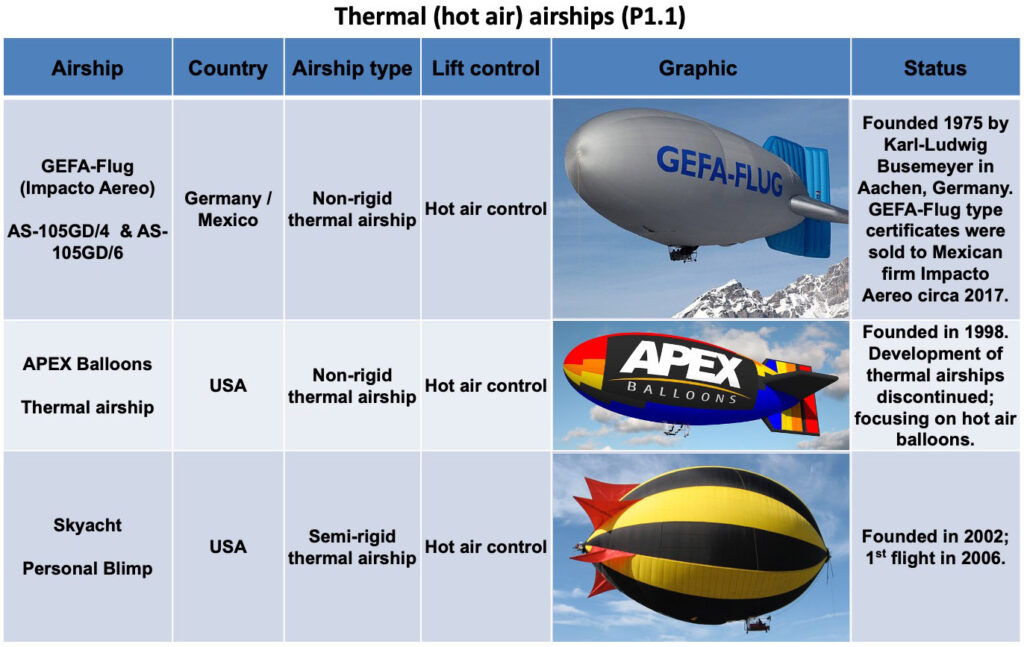
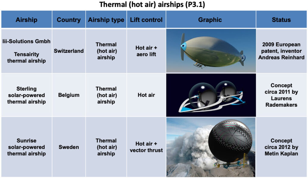
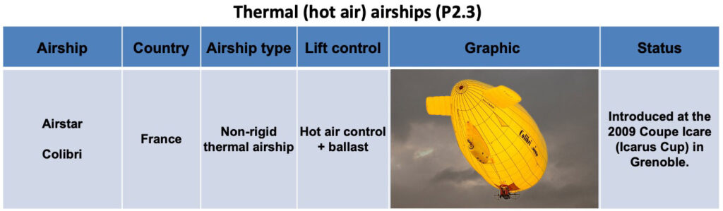
Without hydrogen, the remaining practical choices for lifting gas are helium and hot air. A given volume of hot air can lift only about one-third as much as the same volume of helium, making helium the near-universal choice, with hot air being relegated to a few, small thermal airships and larger thermal-gas (Rozière) airships.
The current high price of helium is a factor in the renewed interest in hydrogen as a lifting gas. It’s also a key selling point for thermal airships. Most helium is produced as a byproduct from natural gas production, hence, helium is not “rare.” However, only a very small fraction of helium available in natural gas currently is recovered, on the order of 1.25%. The remainder is released to the atmosphere. The helium recovery rate could be higher, but is not warranted by the current market for helium. Helium is difficult to store. The cost of transportation to end-users is a big fraction of the market price of helium.
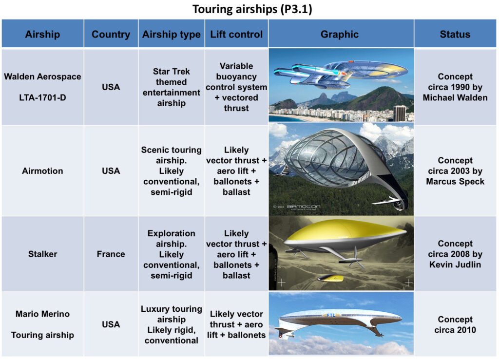
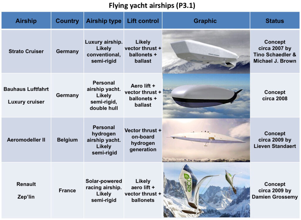
Hydrogen provides 10% more lift than helium. It can be manufactured easily at low cost and can be stored. If needed, hydrogen can be produced with simple equipment in the field. This could be an important capability for recovering an airship damaged and grounded in a remote region. One airship concept described in Modern Airships – Part 3, the Aeromodeller II, is designed for using hydrogen as the lifting gas and as a clean fuel (zero greenhouse gases produced) for its propulsion engines. A unique feature of this airship concept is an on-board system to generate more hydrogen when needed from the electrolysis of water ballast.
A technique for preventing hydrogen flammability is described in Russian patent RU2441685C2, “Gas compound used to prevent inflammation and explosion of hydrogen-air mixtures,” which was filed in 2010 and granted in 2012. This technique appears to be applicable to an airship using hydrogen as its lifting gas. You can read the patent at the following link: https://patents.google.com/patent/RU2441685C2/en
The Canadian airship firm Buoyant Aircraft Systems International (BASI) is a proponent of using hydrogen lifting gas. Anticipating a future opportunity to use hydrogen, they have designed their lifting gas cells to be able to operate with either helium or hydrogen.
Additional regulatory changes will be required to permit the general use of hydrogen in aviation. With the growing interest in the use of hydrogen fuel in aviation, it seems only a matter of time before it is approved for use as a lifting gas in commercial airships.
Even with the needed regulatory changes, the insurance industry will have to deal with the matter of insuring a hydrogen-filled airship.
5. Types of modern airships and aerostats
The term “aerostat” broadly includes all lighter than air vehicles that gain lift through the use of a buoyant gas. Aerostats include unpowered balloons (tethered or free-flying) and powered airships. The following types of airships are described in the Modern Airships series of documents:
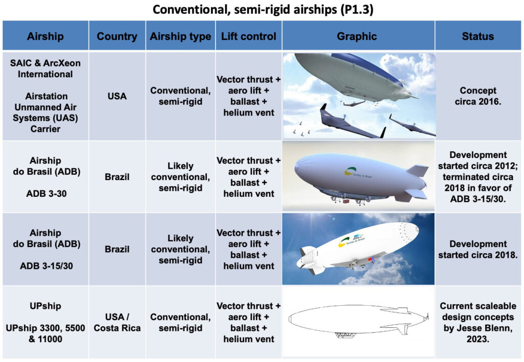
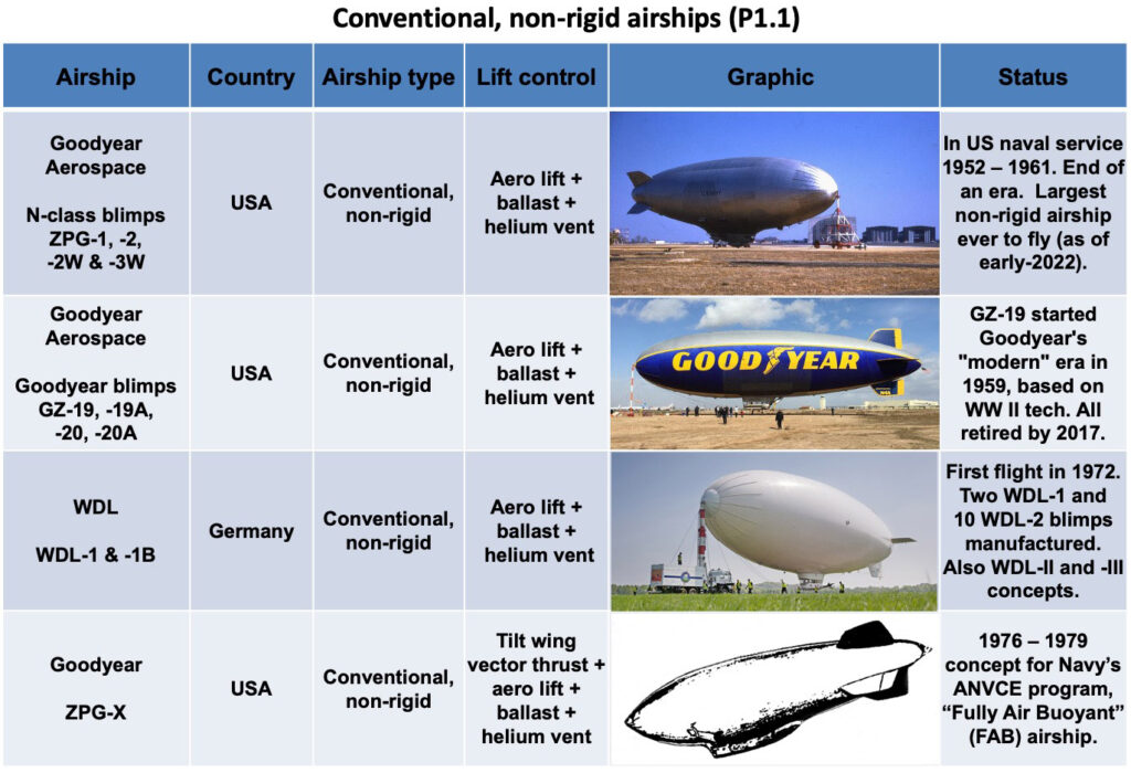
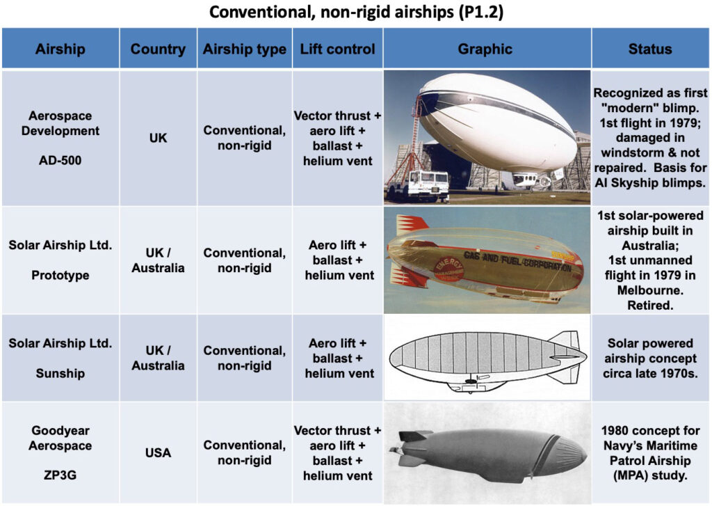
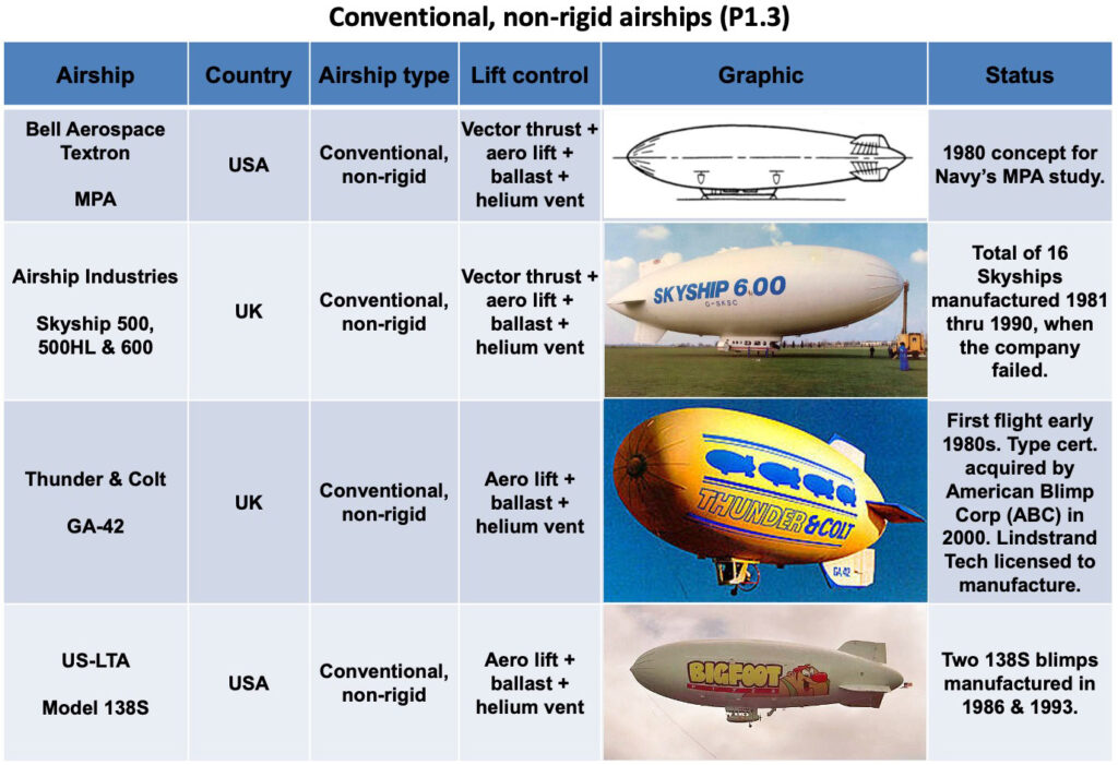
Conventional airships are lighter-than-air (LTA) vehicles that operate at or near neutral buoyancy. The lifting gas (helium) generates approximately 100% of the lift at low speed, thereby permitting vertical takeoff and landing (VTOL) operations and hovering with little or no lift contribution from the propulsion / maneuvering system. Various types of propulsors may be used for cruise flight propulsion and for low-speed maneuvering and station keeping.
Airships of this type include rigid zeppelins, semi-rigid airships and non-rigid blimps.
Rigid airships: These airships have a lightweight, rigid airframe with an outer skin that defines their exterior shape. The airframe supports the gondola, engines and payload. Most have atmospheric pressure lifting gas cells located within the rigid airframe. A special case is a metal-clad rigid airship, with a metal hull that is self-supporting at atmospheric pressure, but typically operates with a slightly positive internal pressure.
Semi-rigid airships: These airships have a rigid structural framework (i.e., a keel or an internal framework) that supports loads and is connected via a load distribution system to a flexible, pressure-stabilized envelope that defines the exterior shape and typically contains air ballonets.
Non-rigid airships (blimps): These airships have a pressure-stabilized, flexible envelope that defines the exterior shape of the airship and typically contains air ballonets. There is no keel or internal structure. Most loads are attached to the gondola and are transferred via a load distribution system to the envelope.
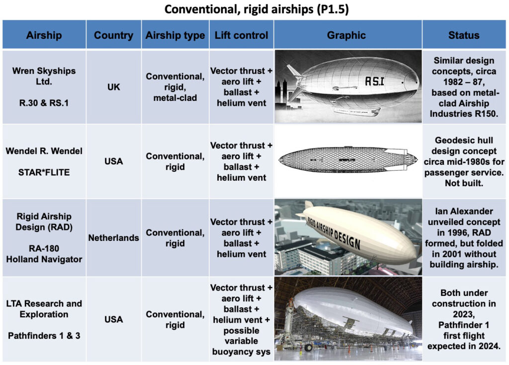
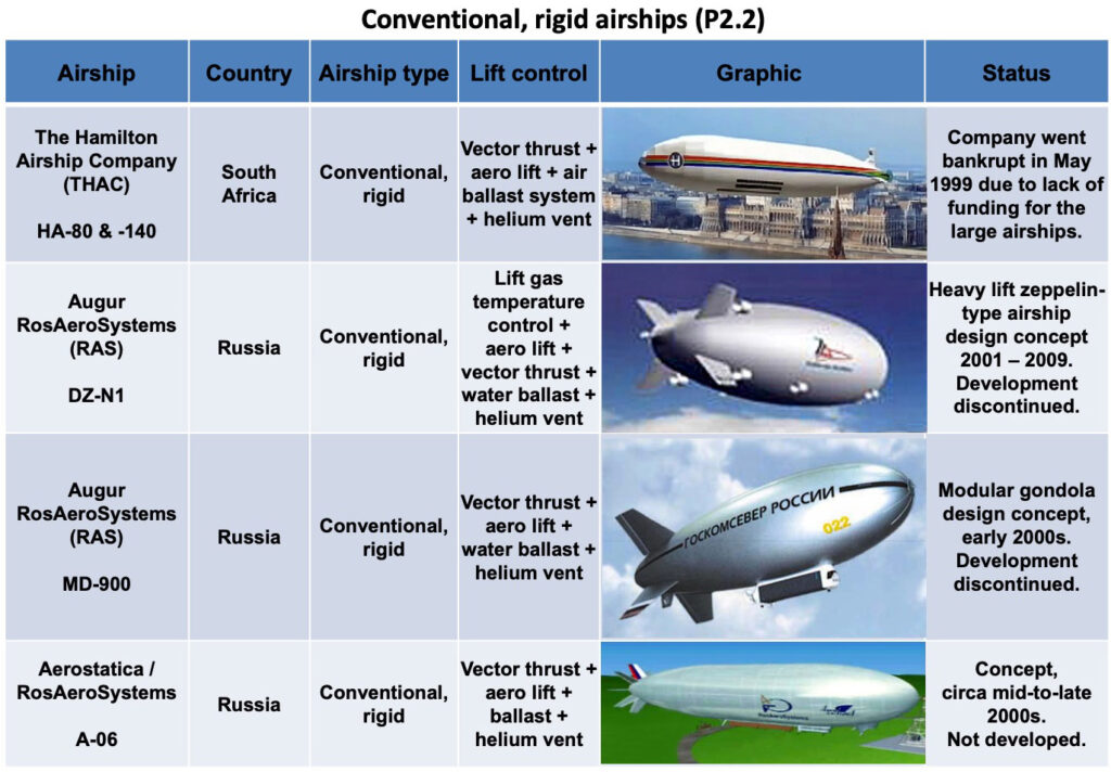
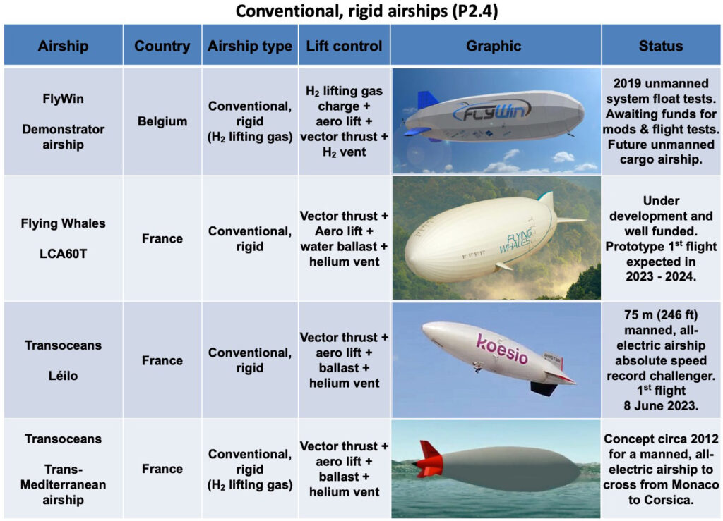
The LTA Research and Exploration Pathfinder 1 and the Flying Whales LCA60T are examples of conventional rigid airships.
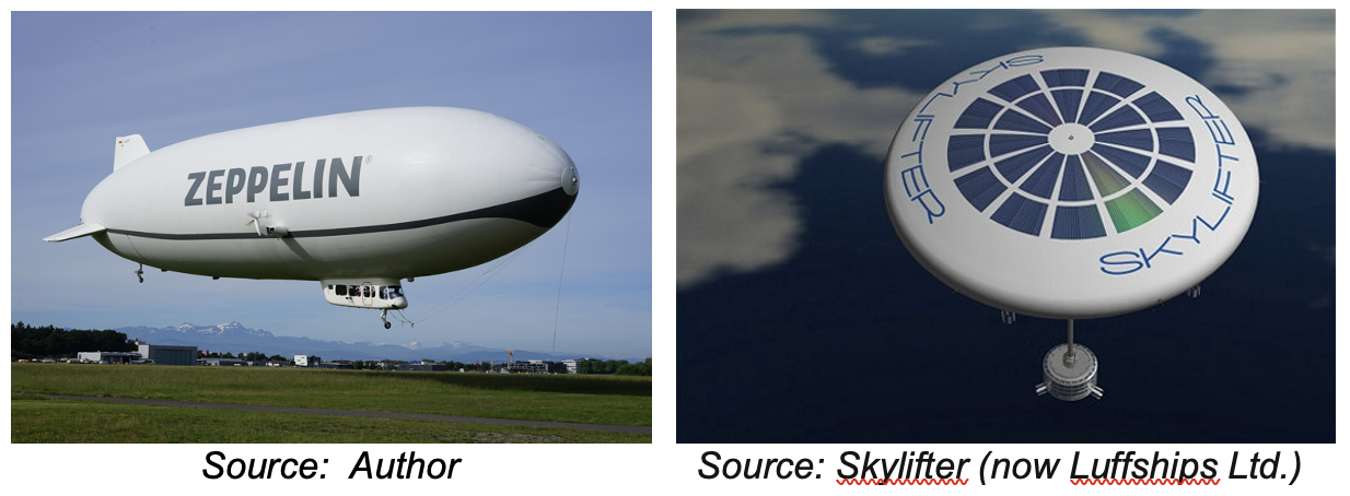
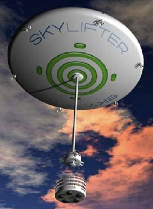
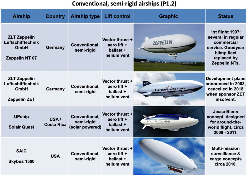
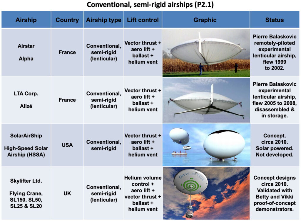
The Zeppelin NT and the SkyLifter are examples of conventional semi-rigid airships.
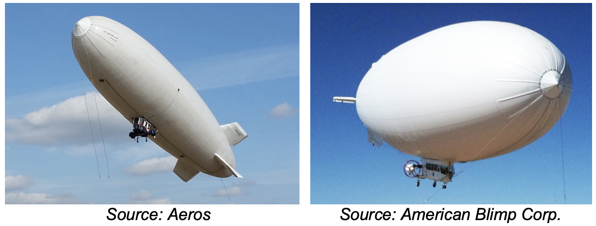
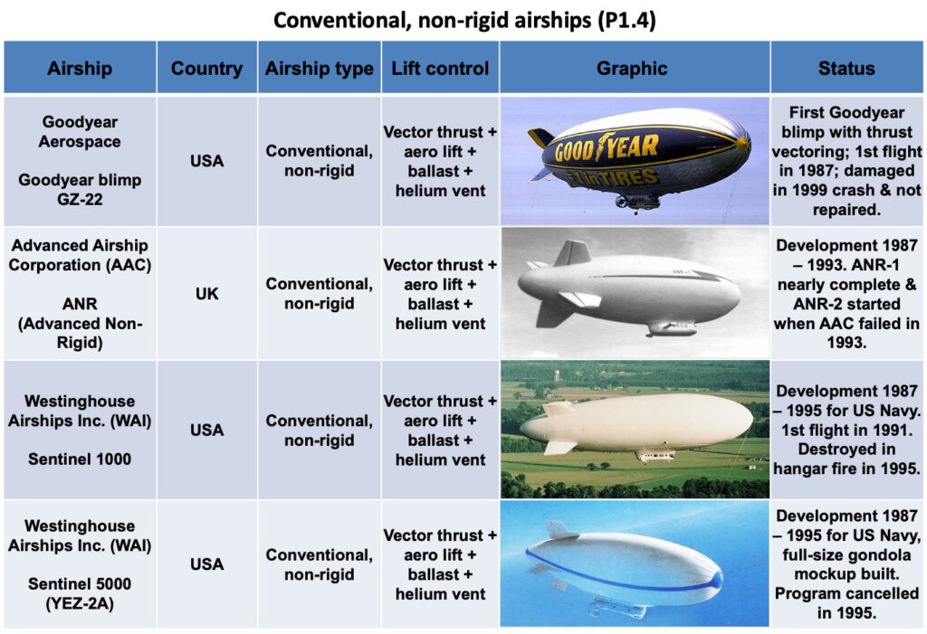
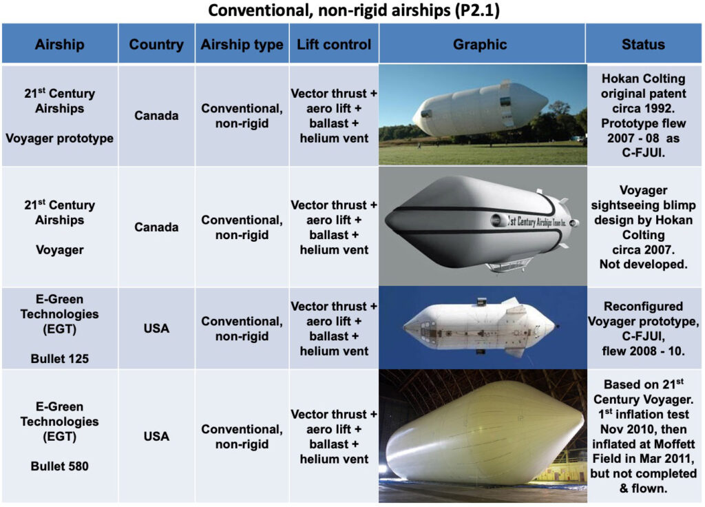
The Aeros 40D Sky Dragon and the American Blimp Corporation MZ-3A (A-170G) are examples of conventional non-rigid airships (blimps).
After being loaded and ballasted before flight, conventional airships have various means to exercise in-flight control over their aerostatic buoyancy, internal pressure and trim. Buoyancy control is exercised with ballast and lifting gas. Internal pressure is controlled with air ballonets and lifting gas vents. Trim is adjusted with the air ballonets or moveable ballast.
Conventional airships with thrust vectoring propulsors have the ability to operate with some degree of net aerostatic heaviness or lightness that can be compensated for with the dynamic thrust (lift or downforce) from the adjustable propulsors.
Controlling buoyancy with ballast
Many conventional airships require adjustable ballast (i.e., typically water or sand) that can be added or removed as needed to establish a desired net buoyancy before flight. Load exchanges (i.e., taking on or discharging cargo or passengers) can change the overall mass of an airship and may require a corresponding ballast adjustment during or after the load exchange.
In-flight use of fuel and other consumables can change the overall mass of an airship. The primary combustion products of diesel fuel are water and carbon dioxide. To reduce the loss of mass from fuel consumption, some airships use a rather complex system to recover water from the engine exhaust. A modern diesel engine water recovery system being developed for the Aerovehicles AV-10 blimp is expected to recover 60% to 70% of the weight of the fuel burned, significantly reducing the change in airship mass during a long mission.
Some Navy blimps and other long-range airships have had a hoist system that could be used in flight to retrieve water from the ocean or any other body of water to increase the amount of on-board ballast.
If an airship becomes heavy, ballast can be dumped in flight to increase aerostatic buoyancy.
Controlling buoyancy with lifting gas
The lifting gas inside an airship may be at atmospheric pressure (most rigid airships) or at a pressure slightly greater than atmospheric (semi-rigid and non-rigid airships). Normally, there is no significant loss (leakage) of lifting gas to the environment. A given mass of lifting gas will create a constant lift force, regardless of pressure or altitude, when the lifting gas is at equal pressure and temperature with the surrounding air. Therefore, a change in altitude will not change the aerostatic lift.
However, temperature differentials between the lifting gas and the ambient air will affect the aerostatic lift produced by the lifting gas. To exploit this behavior, some airships can control buoyancy using lifting gas heaters / coolers to manage gas temperature.
The lifting gas heaters are important for operation in the Arctic, where a cold-soak in nighttime temperatures may result in the lifting gas temperature lagging behind daytime ambient air temperature. This temperature differential would result in a loss of lift until lifting gas and ambient air temperatures were equal.
Conversely, operating an airship in hot regions can result in the lifting gas temperature rising above ambient air temperature (the lifting gas becomes “superheated”), thereby increasing buoyancy. To restore buoyancy in this case, some airships have coolers (i.e., helium-to-air heat exchangers) in the lifting gas cells to remove heat from the lifting gas.
As described by Boyle’s Law, pressure (P) and gas volume (V) are inversely proportional at a constant temperature according to the following relationship: PV = K, where K is a constant. As an airship ascends, atmospheric pressure decreases. This means that a fixed mass of lifting gas will expand within the lifting gas cells during ascent, and will contract within the lifting gas cells during descent. As described previously, this lifting gas expansion and contraction does not affect the magnitude of the aerostatic lift as long as the lifting gas is at equal pressure and temperature with the surrounding air.
If an airship is light and the desired buoyancy cannot be restored with lifting gas coolers, it is possible to vent some lifting gas to the atmosphere to decrease aerostatic lift. Usually there are two types of vents: a manually-operated vent controlled by the pilot and an automatically-operated safety vent designed to protect the envelope from overpressure.
Role of the ballonets
The airship hull / envelope is divided into one or more sealed lifting gas volumes and separate gas volumes called “ballonets” that contain air at ambient, or near-ambient pressure. The ballonets serve as the expansion space that is available for the lifting gas cells as the airship ascends.
The ratio of the total envelope volume to the total ballonet volume is a measure of the expansion space for the lifting gas and is a key factor in determining the airship’s “pressure altitude.” This is the altitude at which the lifting gas cells are fully expanded, and the ballonets are empty. For example, with an envelope volume of 8,255 m3 (290,450 ft3) and a ballonet volume of 2,000 m3 (71,000 ft3), or about 24% of the envelope volume, a Zeppelin NT semi-rigid airship has a reported maximum altitude of 3,000 m (9,842 ft), with the envelope positive pressure of 5 mbar. With a smaller ballonet volume, the Zeppelin NT would have a lower maximum altitude at the specified internal pressure.
In semi-rigid and non-rigid airships with pressure-stabilized hulls, the ballonets are part of the airship’s pressure control system, which automatically maintains the envelope pressure in a desired range. Pressure control is accomplished by changing the volume of the ballonets. An air induction system draws atmospheric air and delivers it at a slight positive pressure (relative to envelope pressure) to increase ballonet volume. An air vent system will discharge air from the ballonets to the ambient atmosphere. While there is a change in mass during these ballonet operations, it is relatively small and does not significantly affect the aerostatic buoyancy of the airship.
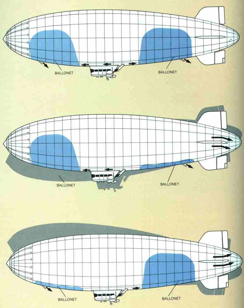
Fore and aft ballonets can be operated individually to adjust the trim (pitch angle) of the airship. Inflating only the fore or aft ballonet, and allowing the opposite ballonet to deflate, will make the bow or stern of the airship slightly heavier and change the pitch angle of the airship without significantly affecting the overall aerostatic buoyancy. These ballonet operating principles are shown in the following diagrams of a blimp with two ballonets, which are shown in blue.
Blimp with two ballonets (blue). Top diagram shows airship with both ballonets full for level cruise flight at low altitude. The middle diagram shows the forward ballonet full and the aft ballonet empty, creating a slightly nose-heavy condition for descending flight. The bottom diagram shows the forward ballonet empty and the aft ballonet full, creating a slightly tail-heavy condition for ascending flight.Source: zeppelinfan.de
5.2 Variable buoyancy airships
Variable buoyancy airships can change their net lift, or “static heaviness,” to become lighter-than-air, neutrally buoyant or heavier-than-air as the circumstances require. Basic characteristics of variable buoyancy airships include the following:
Variable buoyancy airships are capable of VTOL operations and hovering, usually with a full load.
The buoyancy control system may enable in-flight load exchanges from a hovering airship without the need for external ballast.
On the ground, variable buoyancy airships can make themselves heavier-than-air to facilitate load exchanges without the need for external infrastructure or ballast.
It is not necessary for a “light” airship to vent the lifting gas to the atmosphere.
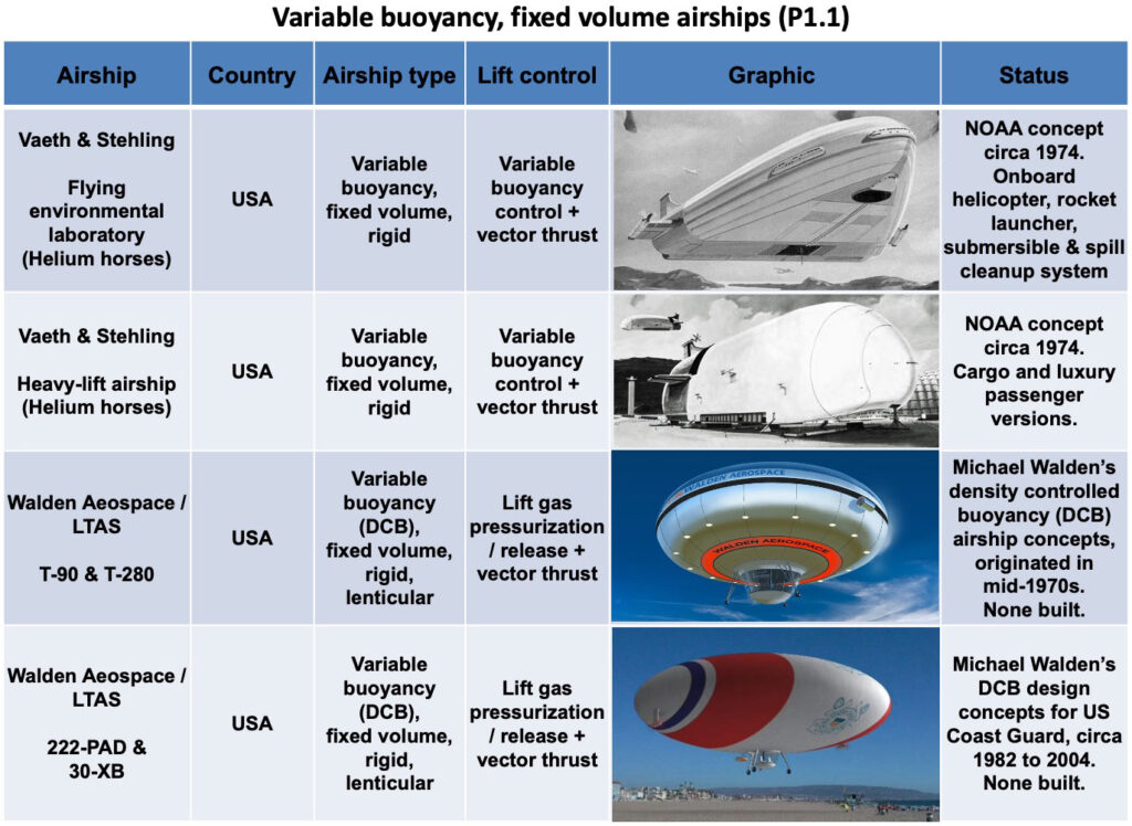
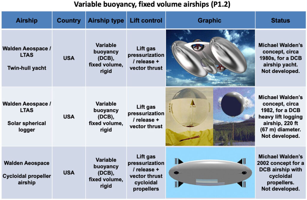
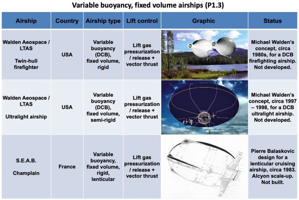
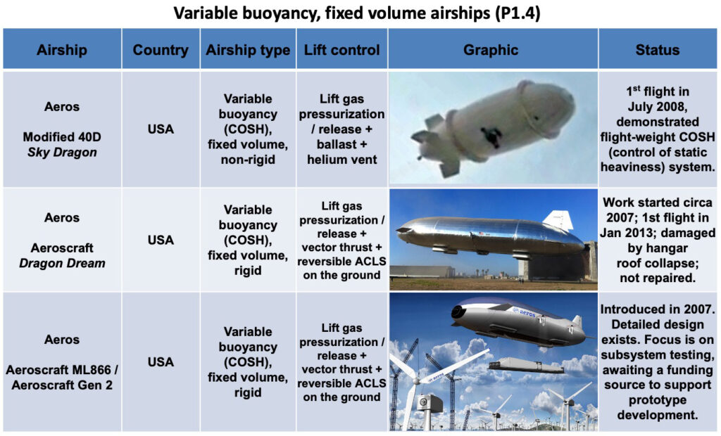
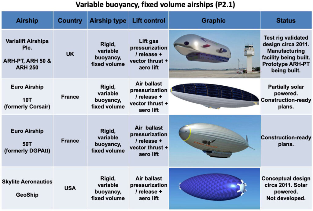
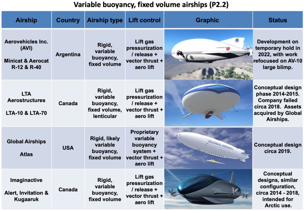
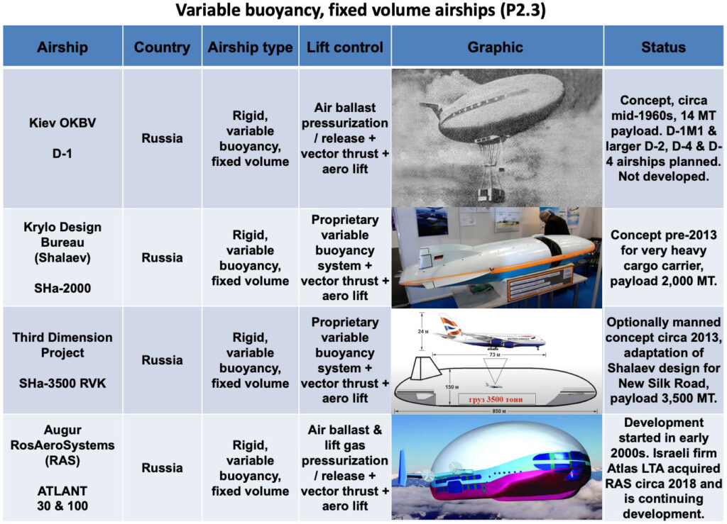
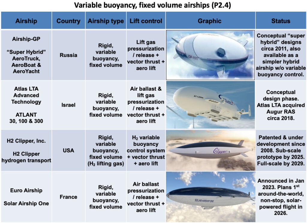
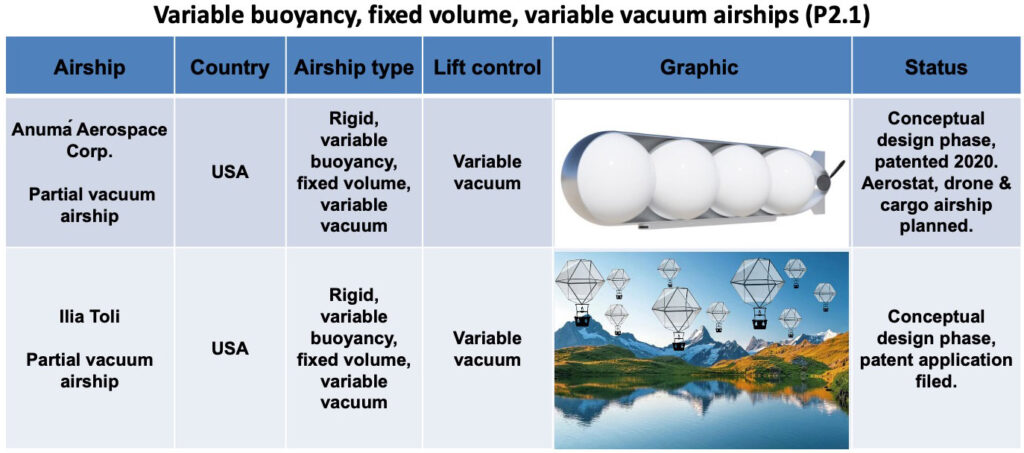
Variable buoyancy, fixed volume airships
Variable buoyancy commonly is implemented by adjusting the density of the lifting gas or a ballast gas, and thereby changing the static heaviness of a fixed volume airship. This also is referred to as density-controlled buoyancy (DCB). For example, a variable buoyancy / fixed volume airship can become heavier by compressing the helium lifting gas or ambient air ballast:
Compressing some of the helium lifting gas into smaller volume tanks aboard the airship reduces the total mass of helium available to generate aerostatic lift.
Compressing ambient air into pressurized tanks aboard the airship adds mass (ballast) to the airship and thus decreases the net lift.
The airship becomes lighter by venting the pressurized gas tanks:
Compressed helium lifting gas is vented back into the helium lifting gas cells, increasing the mass of helium available to generate aerostatic lift.
Compressed air is vented to the atmosphere, reducing the mass of the airship and thus increasing net lift.
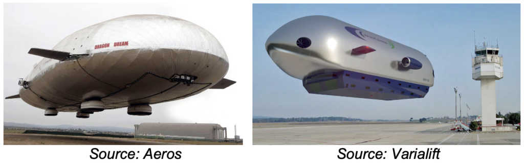
The Aeros Aeroscraft Dragon Dream and the Varilift ARH-50 are examples of variable buoyancy / fixed volume airships.
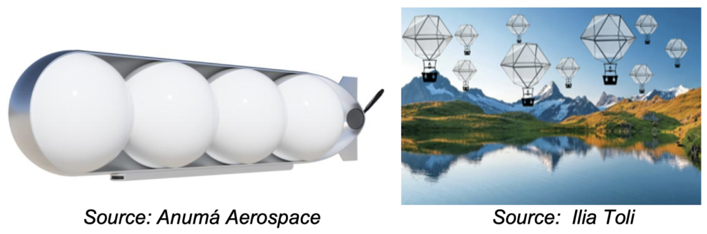
Instead of using a low-density gas to generate aerostatic lift, a vacuum airship uses very low-density air (a partial vacuum) to generate lift, which can be controlled by managing the vacuum conditions inside lightweight, fixed volume structures capable of retaining the vacuum. The key challenge is making the variable vacuum containment and associated systems light enough to generate net lift. Once that has been achieved, then the challenge will be to package that variable buoyancy / variable vacuum system into a functional airship. These challenges have been accepted by Anumá Aerospace and by engineer Ilia Toli.
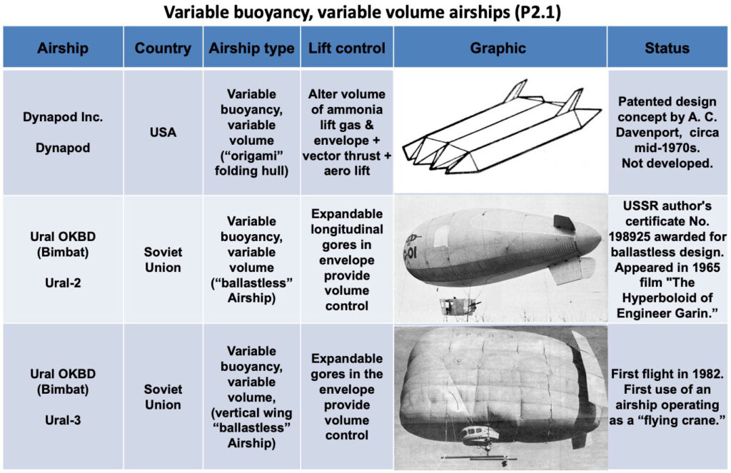
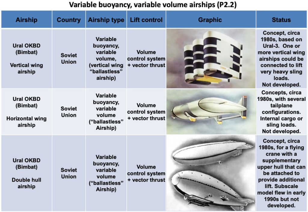
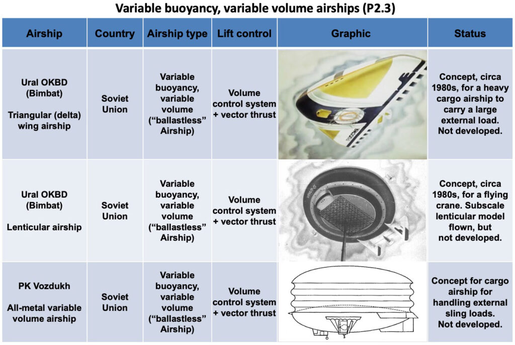
Variable buoyancy, variable volume airships
Variable buoyancy also can be implemented by adjusting the total volume of the helium envelope without changing the mass of helium in the envelope.
As the size of the helium envelope increases, the airship displaces more air and the buoyant force of the atmosphere acting on the airship increases. Static heaviness decreases.
As the size of the helium envelope decreases, the airship displaces less air and the buoyant force of the atmosphere acting on the airship decreases. Static heaviness increases.
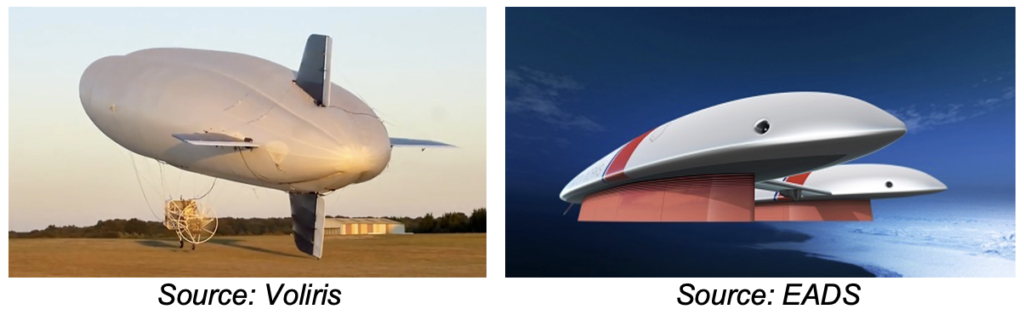
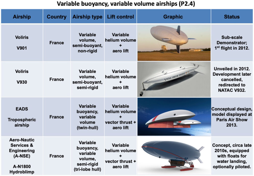
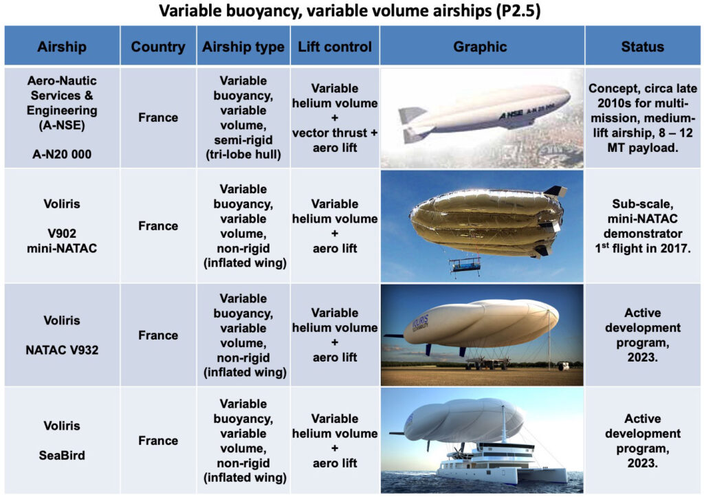
The concept for a variable buoyancy / variable volume airship seems to have originated in the mid-1970s with inventor Arthur Clyde Davenport and the firm Dynapods, Inc. The tri-lobe Voliris airships and the EADS Tropospheric Airship are modern examples of variable buoyancy / variable volume airships.
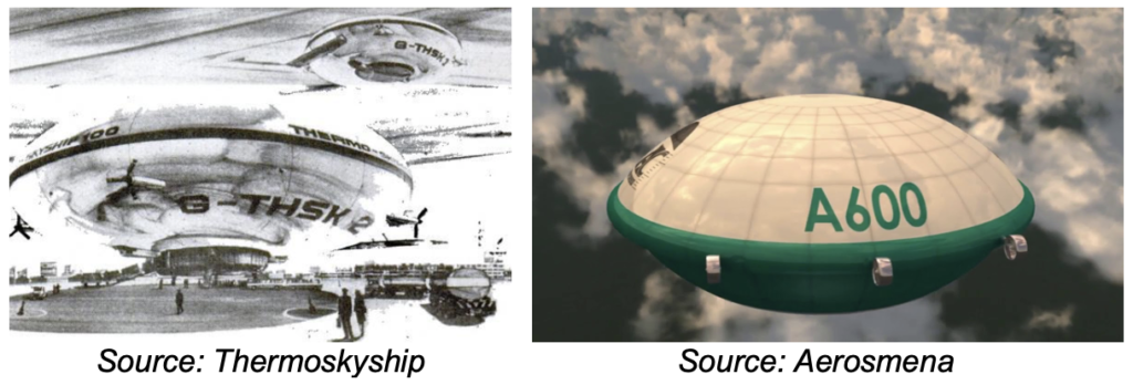
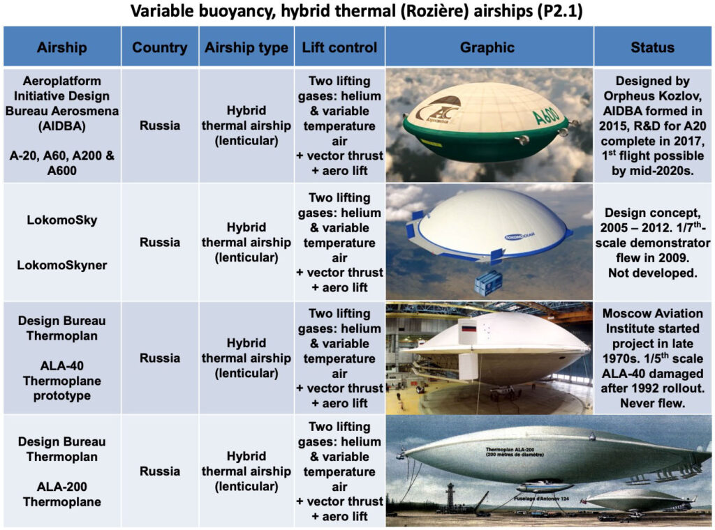
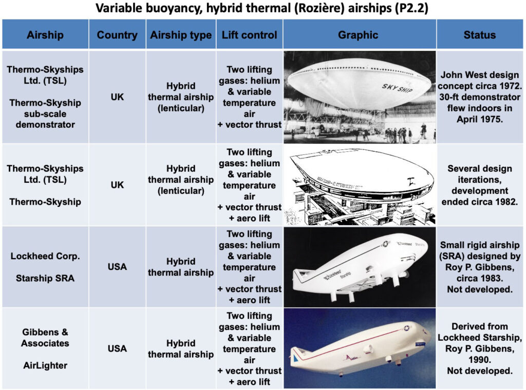
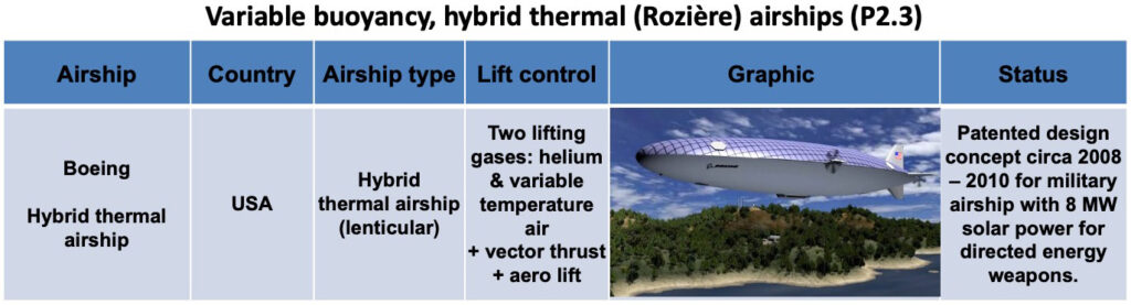
This buoyancy control concept was developed and applied in the 1700s in hybrid balloons designed by Jean-François Pilâtre de Rozière. Such “Rozière” balloons have separate chambers for a non-heated lift gas (hydrogen or helium) and a heated lift gas (air). This concept has been carried over into airships. With helium alone the airship is semi-buoyant (heavier-than-air). Buoyancy is managed by controlling the heating and cooling of the air in a separate “thermal volume.” Examples of hybrid thermal (Rozière) airships are the British Thermo-Skyship (circa 1970s to early 1980s), Russian Thermoplane ALA-40 (circa 1980s to early 1990s), and the heavy-lift Aerosmena (AIDBA) “aeroplatform” currently being developed in Russia. All are lenticular (lens-shaped) airships.
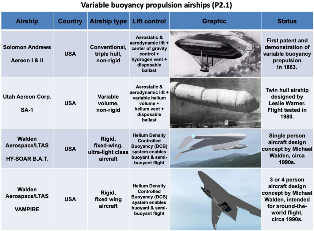
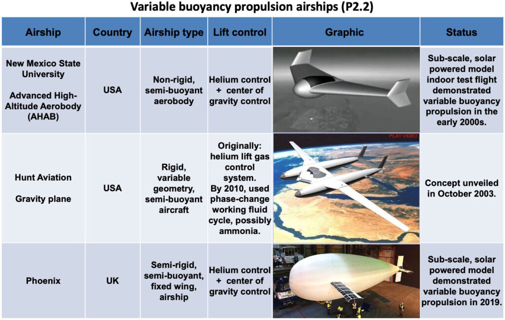
Variable buoyancy propulsion airships / aircraft
Back in the 1860s, Dr. Solomon Andrews invented the directionally maneuverable, hydrogen-filled airship named Aereon that used variable buoyancy (VB) and airflow around the airship’s gas envelope to provide propulsion without an engine.
VB propulsion airships / aircraft fly a repeating sinusoidal flight profile in which they gain altitude as positively buoyant hybrid airships, then decrease their buoyancy at some maximum altitude and continue to fly under the influence of gravity as a semi-buoyant glider. After gradually losing altitude during a long glide, the pilot increases buoyancy and starts the climb back to higher altitude in the next cycle.
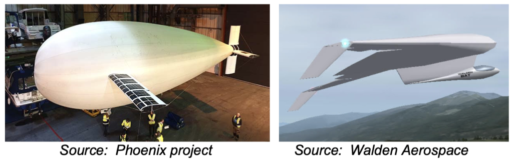
The UK’s Phoenix and Michael Walden’s HY-SOAR BAT concept are two examples of variable buoyancy propulsion airships / aircraft.
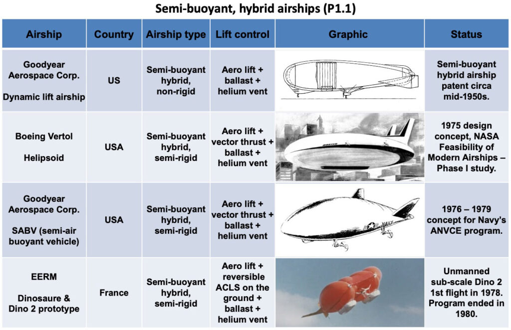
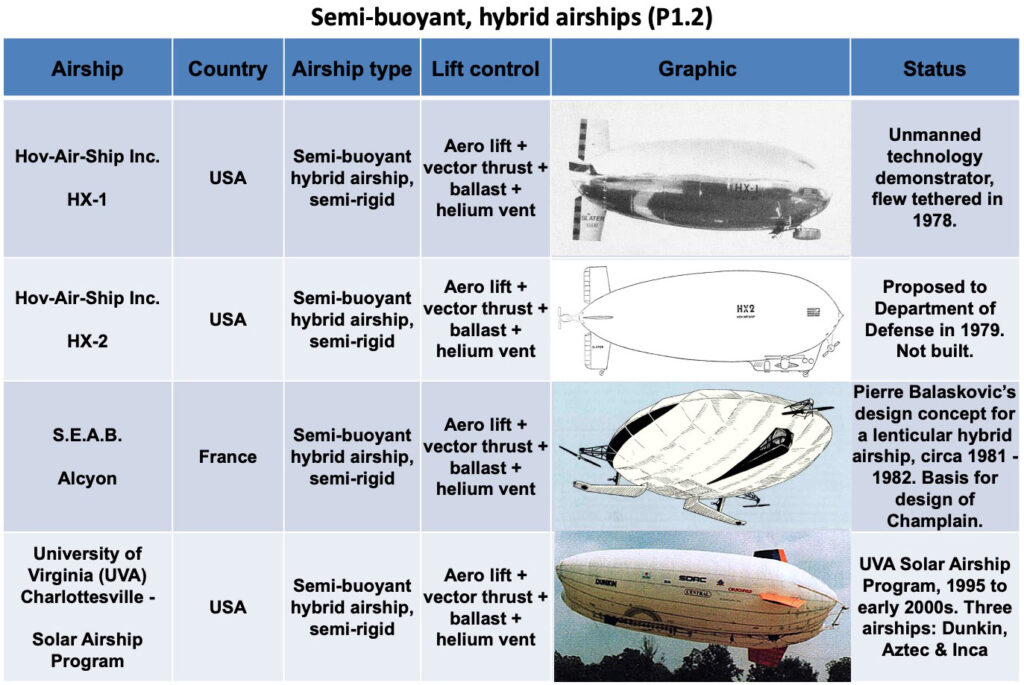
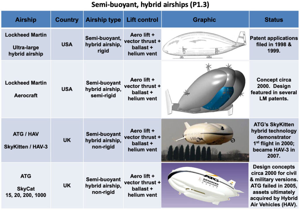
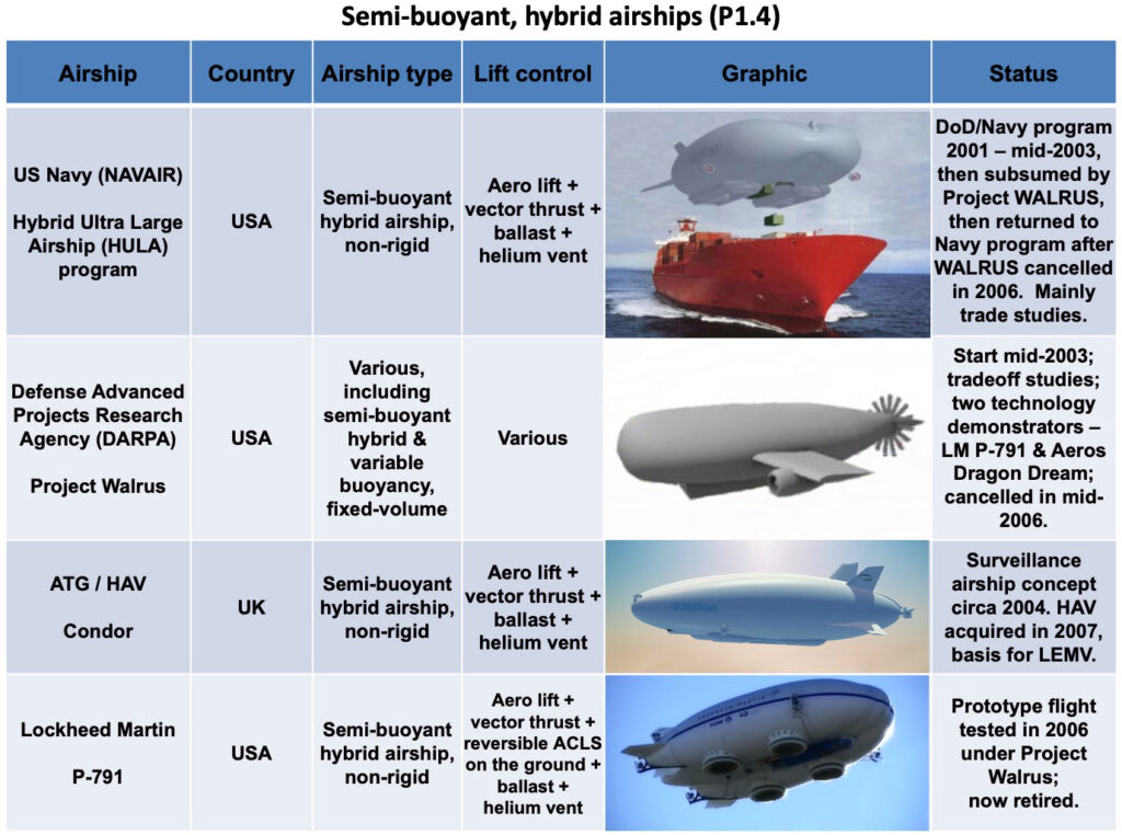
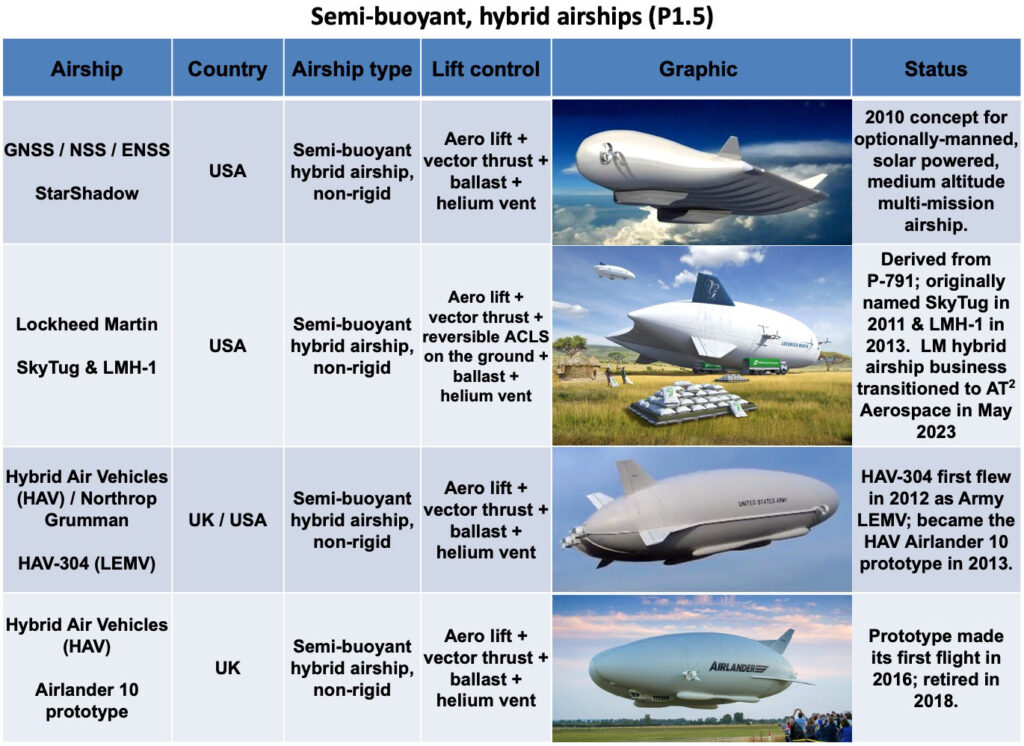
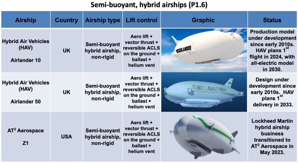
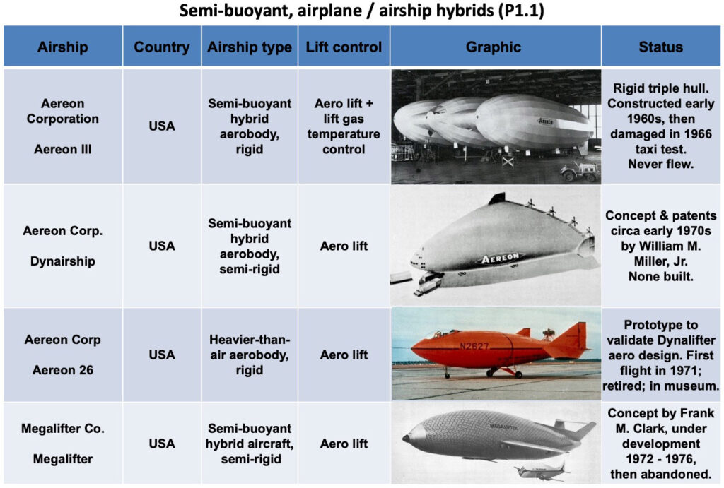
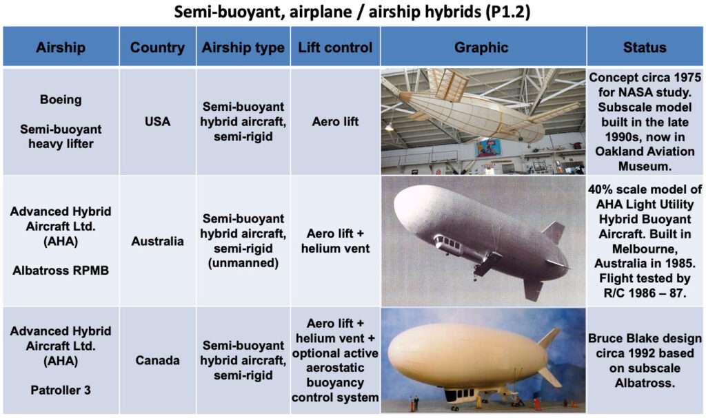
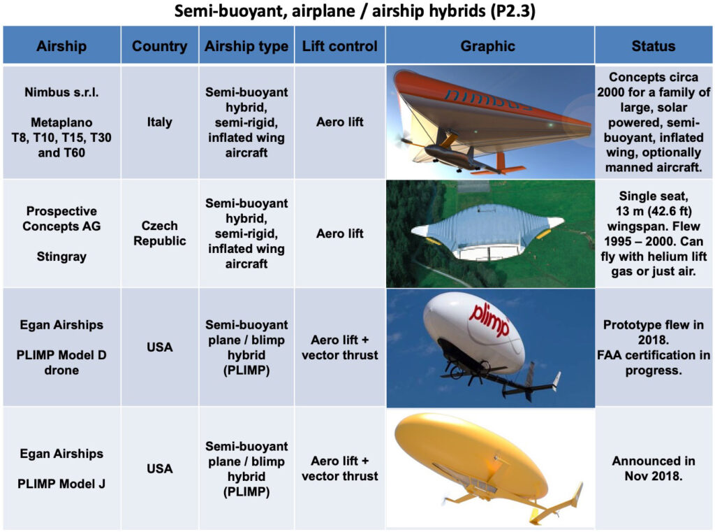
5.3 Semi-buoyant, hybrid air vehicles
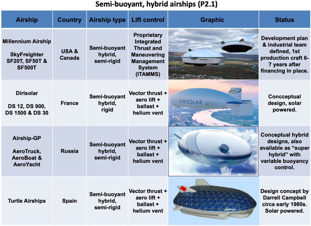
Semi-buoyant, hybrid airships
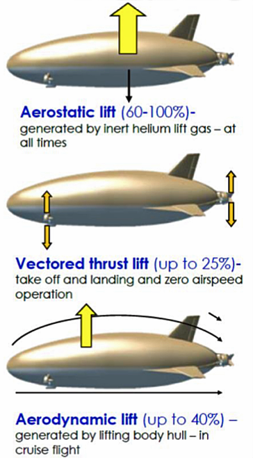
Hybrid airships are heavier-than-air (HTA) vehicles. The term “semi-buoyant” means that the lifting gas provides only a fraction of the needed lift (typically 60 – 80%) and the balance of the lift needed for flight is generated by other means, such as vectored thrust engines and aerodynamic lift from the fuselage and wings during forward flight.
Sources of lift for a semi-rigid, hybrid airship. Source: DoD 2012
Basic characteristics of hybrid airships include the following:
This type of airship requires some airspeed to generate aerodynamic lift. Therefore, it typically makes a short takeoff and landing (STOL).
Some hybrid airships may be capable of limited VTOL operations (i.e., when lightly loaded, or when equipped with powerful vectored thrust engines).
Like conventional airships, the gas envelope in hybrid airship is divided into one or more lifting gas volumes and separate ballonet volumes containing ambient air.
Hybrid airships are heavier-than-air and are easier to control on the ground than conventional airships.
There are three types of hybrid airships: non-rigid, semi-rigid and rigid.
Non-rigid hybrid airships: This type of hybrid airship has a pressure-stabilized, flexible, multi-layer fabric gas envelope that would collapse if the internal pressure were lost. Catenary curtains inside the gas envelope support a gondola and distribute loads into the upper surfaces of the envelope. Ballonets control the pressure inside the gas envelope and can be used to control pitch angle, as on conventional blimps. The wide hybrid airships may have separate ballonets on each side of the inflated envelope that can be used to adjust the roll angle.
Semi-rigid hybrid airships: This type of hybrid airship has a substantial load-carrying, rigid structure, which may be a large keel or a more complex rigid framework inside the gas envelope, that is connected via a load distribution system to the flexible, pressurized envelope that defines the exterior shape and contains air ballonets.
Rigid hybrid airships: This type of hybrid airship has a substantial rigid structure that defines the shape of the exterior aeroshell. The “hard” skin of the airship may be better suited for operation in Arctic conditions, where snow loads and high winds might challenge the integrity of a pressure-stabilized gas envelope on a non-rigid or semi-rigid airship.
The AT2 Aerospace Z1 and the HAV Airlander 10 are examples of large hybrid airships that are under development in 2023. Their propulsion engines are attached directly to reinforced areas of the fabric gas envelope and are supported by localized load distribution systems (i.e., distributed cable stays). Their gas envelopes have no rigid internal structures, and in that respect they resemble blimps.
The Lockheed Martin Aerocraft is an example of a semi-rigid hybrid airship with a substantial, load-carrying, internal rigid structure that enabled the designers to support large propulsion engines in locations that may not otherwise be practical. The AeroTruck being developed by Russian firm Airship-GP is an example of a rigid hybrid airship. The rigid structure is designed for operating in extreme Arctic conditions and parking outdoors where snow loads and icing may be routine problems. Airship-GP also is developing a more complex variable buoyancy model of the AeroTruck.
Semi-buoyant, airplane / airship hybrids
Semi-buoyant airplane / airship hybrids are heavier-than-air, rigid, winged aircraft that carry a large helium volume to significantly reduce the weight of the aircraft and improve its load-carrying capability. Aerostatic lift provides a smaller fraction of total lift for a semi-buoyant aircraft, like a Dynalifter, than it does for a semi-buoyant, hybrid airship.
A semi-buoyant airplane / airship hybrids behaves much like a conventional aircraft in the air and on the ground, and is less affected by wind gusts and changing wind direction on the ground than a hybrid airship.
The semi-buoyant airplane / airship hybrids has some flexibility for loading and discharging cargo without having to be immediately concerned about exchanging ballast, except in windy conditions.
The Aereon Corporation’s Dynairship and the Ohio Airships Dynalifter are examples of semi-buoyant airplane / airship hybrids.
Semi-buoyant, helicopter / airship hybrids
There have been many different designs of helicopter / airship hybrids, including helistats, Dynastats and rotostats. Typically, the airship part of the hybrid craft carries the weight of the craft itself and helicopter rotors deployed in some manner around the airship work in concert to propel the craft and lift and deliver heavy payloads without the need for an exchange of ballast.
The Piasecki PA-97-34J and the Boeing / Skyhook International SkyHook JLH-40 are examples of helistats.
5.4 Stratospheric airships / High Altitude Platform Stations (HAPS)
Stratospheric airships are designed to operate at very high-altitudes, well above the jet stream and in a region of relatively low prevailing winds typically found at altitudes of 60,000 to 75,000 feet (11.4 to 14.2 miles / 18.3 to 22.9 km). This is a harsh environment where airship materials are exposed to the damaging effects of ultraviolet radiation and corrosive ozone. These airships are designed as unmanned vehicles.
Applications for stratospheric airships include military intelligence, surveillance and reconnaissance (ISR) missions, civil environmental monitoring / resource management missions, military / civil telecommunications / data relay functions, and research missions such as high-altitude astronomy. All of these can be long term missions that can last weeks, months or even years.
Typically, the stratospheric airship will operate as a “pseudo-satellite” from an assigned geo-stationary position. Station keeping 24/7 is a unique challenge. Using a hybrid electric power system, these airships can be solar-powered during the day and then operate from an energy storage source (i.e., a battery or regenerative fuel cell) at night. Some propulsion systems, such as propellers that work well at lower altitudes, may have difficulty providing the needed propulsion for station keeping or transit in the very low atmospheric pressure at operating altitude.
The DARPA / Lockheed Martin ISIS airship and the Sceye Inc. high-altitude platform are two examples of stratospheric airships.
5.5 Personal gas airships
Personal airships include a range of small LTA craft, from ultra-light, single seat recreational airships (ULM Class 5) to larger airships with a passenger capacity comparable to a personal automobile. Personal airships typically are conventional non-rigid or semi-rigid airships. They may be powered by various means, including petrol engine, electric motor, or even human-powered.
The French firm Airstar has built and flown several ultra-light airships, such as the all-electric Electroplume 250. Bryan Allen’s White Dwarf is an example of a pedal-powered personal airship.
5.6 Thermal (hot air) airships
Thermal airships use hot air as the lifting gas in place of helium or hydrogen. A given volume of hot air can lift only about one-third as much as the same volume of helium. Therefore, the gas envelope on a thermal airship is proportionally larger than it would be on a comparable airship using helium as the lifting gas.
The non-rigid GEFA-Flug four-seat AS-105GD/4 and six-seat AS-105GD/6, and the semi-rigid, two-seat Skyacht Personal Blimp are examples of current thermal airships that use propane burners to produce the hot air for lift. Pitch can be controlled with fore and aft burners. There are no ballonets.
Advanced concepts for solar-powered thermal airships are described in Modern Airships – Part 3.
5.7 Hybrid rocket / balloon (Rockoon) airships
The term “Rockoon” has been used to refer to a ground-launched, high-altitude balloon that carries a small sounding rocket aloft to be launched in the stratosphere, perhaps 15 to 20 miles (24 to 32 km) above the ground. Starting the rocket’s powered flight at high-altitude enables it to reach a much higher altitude than from a conventional ground launch.
Airship designers Michael Walden (LTAS / Walden Aerospace) and John Powell (JP Aerospace) have applied the rocket / balloon hybrid concept more broadly to produce several diverse design concepts for airships capable of operating in the stratosphere, in near-space, and all the way to Earth orbit.
For more than a decade, JP Aerospace has been developing electric / chemical MHD (magnetohydrodynamic) hybrid plasma engines for use in their planned Trans-atmospheric and Orbital Ascender airships.
5.8 Electro-kinetically (EK) propelled airships
EK propulsion uses electrostatic and/or electromagnetic fields to generate thrust, typically a rather low thrust with currently available hardware. In principle, EK propulsion could be used in place of conventional propulsion means, such as propellers and turbine engines, particularly on airships that operate in the stratosphere.
EK propulsion has been demonstrated experimentally with small, neutrally-buoyant airships, such as Michael Walden’s (LTAS / Walden Aerospace) XEM-1 rigid, hybrid EK drive demonstrator that first flew in 1974, and the graceful, non-rigid b-IONIC Airfish that was developed and flown in 2005 by the German firm Festo.
5.9 LTA drones
LTA drones are uncrewed airships that may be flown by remote control or by onboard control systems with varying degrees of autonomy. Such drones are being developed worldwide. Many LTA drones are small, conventional, elliptical or cylindrical hull airships. However, other designs, including twin-hull, spherical, lenticular and inflated delta wing have been developed and flown. Many are all-electric, and some have a photovoltaic solar array to help increase their range and operational flexibility.
Two examples of modern, autonomous, all-electric LTA drones are the Cloudline cargo drone developed in South Africa and being operationally tested since mid-2023, and Kelluu’s persistent aerial monitoring drone developed and being tested in Finland, along with an information management infrastructure for rapidly delivering processed data to clients.
5.10 Unpowered aerostats
Unpowered aerostats include tethered and free-flying balloons used in a wide variety of applications. These vehicles are not “airships.”
Tethered aerostats (kite balloons)
Many firms offer tethered aerostats for missions such as persistent surveillance and environmental monitoring, with instruments carried on the aerostat to an operating altitudes ranging from of several hundreds to several thousands of meters. The tether may be a simple steel or composite material cable (i.e., Kevlar), or it may be a powered tether that delivers electrical power to aerostat and payload systems and establishes a secure fiber optic data link between the aerostat and its ground station.
Examples are the T-C350 from the French firm A-NSE and the medium volume tethered aerostat from the Israeli firm Atlas LTA Advanced Technology.
Tethered manned aerostats
Tethered manned aerostats commonly are used in two application, as tourist sightseeing balloons and as parachute training balloons. Both applications require flying at relatively low altitude (305 m / 1,000 ft) with up to 30 tourist passengers or 8 – 10 parachute trainees. Spherical balloons are common for tourist flights. The latest Lindstrand manned aerostat has a more aerodynamic shape, like many unmanned tethered aerostats, and is able to operate in stronger wind conditions than a spherical manned aerostat.
Tethered LTA wind turbines
Tethered buoyant wind turbines operate at altitudes of hundreds to thousands of feet above the ground, where stronger prevailing winds offer more energy for harvesting than at ground level. These tethered aerostats (kite balloons) carry one or more compact, wind-driven electric power generating systems that deliver power via the tether to a substation on the ground, and then onward to a regional electrical grid.
Two examples that have been tried, but not (yet) commercialized, are the Altaeros Energies BAT and the Magenn Air Rotor System (MARS).
New, but untried airborne wind turbine systems are being developed in 2023 by Aeerstatica Energy Airships and by AirbineTM Renewable Energy Systems (ARES).
Tethered heavy lifter balloons
Another tethered aerostat application is as a heavy load lifter. In this application, the aerostat may be tethered at a fixed site to function as an heavy lift crane, replacing a conventional construction crane. The tethered aerostat may be designed for a mobile application, lifting a payload and being towed to a delivery site by a vehicle on the ground, a helicopter or by some other means.
Examples are the German CargoLifter AG CL75-AC Air Crane, which flew in 2002, and AirBarge designed by the successor firm, CL Cargolifter GmbH and Co KGaA.
Some aerostats are designed to operate on a tether and, on command, detach and continue the mission as a free-flying airship. This hybrid vehicle can operate on station for a long period of time as an tethered aerostat until something of interest is detected. Then the vehicle detaches and flies away to provide a closeup investigation at the point of interest.
Examples are the Sanswire / WSGI Argus One Hybrid aerostat / UAV and the Detachable Airship from a Tether (DATT) being developed by UAV Corp.
Free-flying, high-altitude balloons
Free-flying balloons can provide relatively low-cost access to the stratosphere. Zero-pressure balloons can lift large payloads (up to thousands of kilograms) to altitudes up to about 45,000 meters (147,638 ft / 28.0 miles) on missions lasting up to a week. Superpressure balloons can remain aloft much longer than zero-pressure balloons and can be deployed on missions of several months, but with smaller payloads. Several firms offer stratospheric assess with free-flying balloons, including Airstar Aerospace, Aerostar/TCOM, Zero 2 Infinity and JP Aerospace.
Free-flying, manned, high-altitude balloons
There are many firms developing pressurized passenger capsules to carry “space tourists” to altitudes up to about 40 km (25 miles) under very large stratospheric balloons. These flights will include a couple of hours to view the Earth from maximum altitude. After initial descent under the balloon, most of the capsules return to Earth under a parachute or parafoil with a landing on the ground or in the sea. The balloon typically is not recovered. Full-scale system test flights are expected to begin in 2024, with initial passenger flights by 2025.
6. How does an airship pick up and deliver a heavy load?
The term “load exchange” refers to the pickup and delivery of cargo by an airship, with or without an exchange of external ballast to compensate for the mass of cargo being moved on or off the airship. This isn’t a simple problem to solve.
The problem of buoyancy control
In Jeanne Marie Laskas’ article, Igor Pasternak, CEO of airship manufacturer Worldwide Aeros Corp. (Aeros), commented on the common problem facing all airships when a heavy load is delivered:
“The biggest challenge in using lighter-than-air technology to lift hundreds of tons of cargo is not with the lifting itself—the larger the envelope of gas, the more you can lift—but with what occurs after you let the stuff go. ‘When I drop the cargo, what happens to the airship?’ Pasternak said. ‘It’s flying to the moon.’ An airship must take on ballast to compensate for the lost weight of the unloaded cargo, or a ground crew must hold it down with ropes.”
Among the many current designers and manufacturers of large airships, the matter of maintaining the airship’s net buoyancy within certain limits while loading and unloading cargo and passengers is handled in several different ways depending on the type of airship involved. Some load exchange solutions require ground infrastructure at fixed bases and/or temporary field sites for external ballast handling, while others require no external ballasting infrastructure and instead use systems aboard the airship to adjust buoyancy to match current needs or provide vectored thrust (or suction) to temporarily counteract the excess buoyancy. The solution chosen for managing airship buoyancy during a load exchange strongly influences how an airship can be operationally employed and where it can pickup and deliver its payload.
Additional problems for airborne load exchanges
Several current designers and manufacturers of large airships report that their airships will have the ability to conduct airborne load exchanges of cargo from a hovering airship. Jeremy Fitton, the Director of SkyLifter, Ltd., described the key issues affecting a precision load exchange executed by a hovering airship as follows:
“The buoyancy management element of (an airborne) load-exchange is not the main control problem for airships. Keeping the aircraft in a geo-stationary position – in relation to the payload on the ground – is the main problem, of which buoyancy is a component.”
The matters of precisely maintaining the airship’s geo-stationary position throughout an airborne load exchange and controlling the heading of the airship and the suspended load are handled in different ways depending on the type of airship involved. The time required to accomplish the airborne load exchange can be many minutes or much longer, depending on the weight of the cargo being picked up or delivered and the time it takes for the airship to adjust its buoyancy for its new loaded or unloaded condition. Most of the airships offering an airborne load exchange capability are asymmetrical (i.e., conventional “cigar shaped” or hybrid aerobody-shaped) and must point their nose into the wind during an airborne load exchange. Their asymmetrical shape makes these airships vulnerable to wind shifts during the load exchange. The changing cross-sectional area exposed to the wind complicates the matter of maintaining a precise geo-position with an array of vectoring thrusters.
During such a delivery in variable winds, even with precise geo-positioning over the destination, the variable wind direction may require the hovering airship to change its heading slightly to point into the wind. This can create a significant hazard on the ground, especially when long items, such as a wind turbine blade or long pipe segment are being delivered. For example, the longest wind turbine blade currently in production is the GE Haliade-X intended for off-shore wind turbine installations. This one-piece blade is 107 meter (351 ft) long. A two degree change in airship heading could sweep the long end of the blade more than three meters (10 feet), which could be hazardous to people and structures on the ground.
Regulatory requirements pertaining to load exchanges
The German / Netherlands “Transport Airship Requirements” (TAR), includes the following requirement for load exchanges in TAR 80, “Loading / Unloading”:
(c) During any cargo exchange…the airship must be capable of achieving a safe free flight condition within a time period short enough to recover from a potentially hazardous condition.”
Similar requirements exist in the EASA proposed Special Conditions published in February 2021, in SC GAS.2125, “Loading / Unloading.”
These requirements will be a particular challenge for airships designed to execute an airborne load exchange from a hovering airship.
The CargoLifter approach to an airborne load exchange
One early approach for delivering a load from a hovering airship was developed for the CargoLifter CL160. As described on the Aviation Technology website (https://www.aerospace-technology.com/projects/cargolifter/), the CL160 would have performed an in-flight delivery of cargo as follows:
“The airship hovers at about 100 m above the ground and a special loading frame, which is fixed during flight to the keel of the airship, is then rigged with four cable winches to the ground, a procedure which is to assure that the airship’s lifting gear stays exactly above the desired position. Ballast water is then pumped into tanks on the frame and the payload can be unloaded. The anchor lines are released and the frame is pulled back into the payload bay of the airship.”
In a 2002 test using the heavy-lift CargoLifter CL75 aerostat as an airship surrogate, a 55 metric ton German mine-clearing tank was loaded, lifted and discharged from the loading frame as water ballast was unloaded and later reloaded in approximately the same time it took to secure the tank in the carriage (several minutes). In this test, the 55 metric tons cargo was exchanged with about 55 cubic meters (1,766 cubic feet, 14,530 US gallons) of water ballast.
The SkyLifter approach to an airborne load exchange
One airship design, the SkyLifter, addresses the airborne load exchange issues with a symmetrical, disc-shaped hull that presents the same effective cross-sectional area to a wind coming from any direction. With the aid of cycloidal propellers, his airship is designed to move equally well in any direction (omni-directional), simplifying airship controls in changing wind conditions, and likely giving the SkyLifter an advantage over other designs in maintaining a precise geolocation above a site while conducting an airborne load exchange without the need for the system of ground tethers used by the CL160
Some of the advanced airship concepts being developed, especially for future heavy-lift cargo carriers, will result in extremely large air vehicles on a scale not seen since the heyday of the giant zeppelins in the 1930s. Consider the following semi-rigid hybrid airships shown to scale with contemporary US Air Force fixed-wing cargo aircraft.
Size comparison for hybrid airships sized for various lift applications. Source: DoD 2012
8. Graphic tables
The airships and aerostats reviewed in Modern Airships – Part 1 are summarized in the following set of graphic tables that are organized into the airship type categories listed below:
Within each category, each page of the table is titled with the name of the airship type category and is numbered (P1.x), where P1 = Modern Airships – Part 1 and x = the sequential number of the page in that category. For example, “Conventional, rigid airships (P1.2)” is the page title for the second page in the “Conventional, rigid airships” category in Part 1. There also are conventional, rigid airships addressed in Modern Airships – Part 2. Within a category, the airships are listed in the graphic tables in approximate chronological order.
Links to the individual Part 1 articles on these airships are provided in Section 10. Some individual articles cover more than one particular airship. Have fun exploring!
9. Assessment of near-term LTA market prospects
Among the new airships described in Part 1, the following advanced airship seems to be the best candidate for achieving type certification in the next five years:
LTA Research and Exploration (USA): Pathfinder 1 rigid airship, which is expected to make its first flight in 2024. The program appears to be well funded.
The following airship manufacturers in Part 1 have advanced designs and they seem to be ready to manufacture a first commercial prototype if they can arrange adequate funding:
AT2 Aerospace (USA): Their Z1 hybrid airship formerly was known as the Lockheed Martin LMH-1. In May 2023, Lockheed Martin exited the hybrid airship business without completing type certification and transitioned that business, including intellectual property and related assets, to the newly formed, commercial company AT2 Aerospace. In June, Straightline Aviation (a former LMH-1 customer) signed a Letter of Intent with AT2 Aerospace, signaling commercial support for the Z1 hybrid airship.
Aeros (USA): It seems that Aeros has been ready for more than a decade to begin type certification and manufacture a prototype of their Aeroscraft ML866 / Aeroscraft Gen 2 variable buoyancy / fixed volume airship. The firm has reported successful subsystem tests.
Recent changes in European aviation regulations reduce some of the regulatory uncertainty for advanced airship type certification in the EU. The US FAA has not yet published comparable guidance for advanced airships, resulting in continuing regulatory uncertainty in the USA.
The promising airships in Part 1, as listed above, will be competing in the worldwide airship market with candidates identified in Modern Airships – Part 2, which potentially could enter the market in the same time frame. Among the airships described in Part 2, the following advanced airship seems to be the best candidate for achieving type certification in the next five years:
Flying Whales (France): The LCA60T rigid cargo airship was significantly redesigned in 2021, which resulted in a considerable schedule delay. In March 2023, Flying Whales reported that they expected to complete construction and flight testing of the first production prototype in the 2024 – 2025 timeframe, followed by EASA certification and start of industrial production in 2026. The project appears to be well funded from diverse international sources in France, Canada, China and Morocco. Full-scale production facilities are planned in France, China and Canada and commercial airship operating infrastructure is being planned.
Hybrid Air Vehicles (UK): The Airlander 10 commercial passenger / cargo hybrid airship is being developed by HAV based on their experience with the Airlander 10 prototype, which flew from 2016 to 2017. In 2022, Valencia, Spain-based Air Nostrum, which operates regional flights, ordered 10 Airlander 10 aircraft, with delivery scheduled for 2026. Also in 2022, Highlands and Islands Airport (HIAL) sponsored a study for introducing the Airlander 10 in Scotland. In April 2023, the regional UK government of South Yorkshire concluded a financial agreement that is expected to lead to the Airlander 10 being manufactured in Doncaster, in the north of England. Things are moving in the right direction. However, FutureFlight reported that “the plan cannot proceed unless HAV secures a strategic investor. It needs at least £100 million to begin construction.”
The following airship manufacturers in Part 2 have advanced designs and they seem to be ready to manufacture a first prototype if they can arrange funding:
Aerovehicles (USA / Argentina): They claim their AV-10 non-rigid, multi-mission blimp can carry a 10 metric ton payload and be type certified within existing regulations for blimps. This should provide a lower-risk route to market for an airship with an operational capability that does not exist today.
Atlas LTA Advanced Technology (Israel): After acquiring the Russian firm Augur RosAeroSystems in 2018, Atlas is continuing to develop the ATLANT variable buoyancy, fixed volume heavy lift airship. They also are developing a new family of non-rigid Atlas-6 and -11 blimps and unmanned variants. However, the development plans and schedules have not yet been made public.
BASI (Canada): The firm has a well-developed design in the MB-30T and a fixed-base operating infrastructure design that seems to be well suited for their primary market in the Arctic.
Euro Airship (France): The firm reports having production-ready plans for their rigid airship designs. In June 2023, Euro Airship announced plans to build and fly a large rigid airship known as Solar Airship One around the world in 2026.
Millennium Airship (USA & Canada): The firm has well developed designs for their SF20T and SF50T SkyFreighters, has identified its industrial team for manufacturing, and has a business arrangement with SkyFreighter Canada, Ltd., which would become a future operator of SkyFreighter airships in Canada. In addition, their development plan defines the work needed to build and certify a prototype and a larger production airship.
The 2020s will be an exciting time for the airship industry. We’ll finally get to see if the availability of several different heavy-lift airships with commercial type certificates will be enough to open a new era in airship transportation. Aviation regulatory agencies need to help reduce investment risk by reducing regulatory uncertainty and putting in place an adequate regulatory framework for the wide variety of advanced airships being developed. Customers with business cases for airship applications need to step up, place firm orders, and then begin the pioneering task of employing their airships and building a worldwide airship transportation network with associated ground infrastructure. This will require consistent investment over the next decade or more before a basic worldwide airship transportation network is in place to support the significant use of commercial airships in cargo and passenger transportation and other applications. Perhaps then we’ll start seeing the benefits of airships as a lower environmental impact mode of transportation and a realistic alternative to fixed-wing aircraft, seaborne cargo vessels and heavy, long-haul trucks.
10. Links to the individual articles
The following links will take you to the individual Modern Airships – Part 1 articles. The organization of the following list matches the graphic table.
Note that several of these articles address more than one airship design from the same manufacturer / designer and they may be in different categories (i.e., Airship Industries, Ohio Airships, Walden Aerospace). These designs are listed separately in the above graphic tables and in the following index. The links listed below will take you to the correct article.
“Modern Airships” is a three-part document that contains an overview of modern airship technology in Part 1 and links in Parts 1, 2 and 3 to more than 275 individual articles on historic and advanced airship designs. This is Part 3. Here are the links to the other two parts:
To help you navigate the large volume of material in these three documents, please refer to following indexes. The first index simply lists the article titles in alphabetic order within each Part.
Parts 1 & 2 address similar types of airships and unpowered aerostats. The following airship type index enables you to see all of the airships and aerostats addressed in Parts 1 & 2, grouped by type, with direct links to the relevant articles.
The airships described in Part 3 are relatively exotic concepts in comparison to the more utilitarian and heavy-lift airships that dominate Parts 1 and 2. As shown in the following index, the airships in Part 3 are organized by function rather than airship type, which sometimes is difficult to determine with the information available.
Modern Airships – Part 3 begins with a graphic table identifying the airship concepts addressed in this part, and concludes by providing links to more than 50 individual articles on these airship concepts. A downloadable pdf copy of Part 3 is available here:
If you have any comments or wish to identify errors in these documents, please send me an e-mail to: [email protected].
I hope you’ll find the Modern Airships series to be informative, useful, and different from any other single document on this subject.
Best regards,
Peter Lobner
17 March 2024
Record of revisions to Part 3
Original Modern Airships post, 26 August 2016: addressed 14 airships in a single post.
Expanded the Modern Airships post and split it into three parts, 18 August 2019: Part 3 included 32 linked articles.
Part 3, Revision 1, 21 December 2020: Added 1 new article on Walden Aerospace. Part 3 now had 33 articles
Part 3, Revision 2, 8 February 2022: Added 14 new articles, moved over and updated the Halo article from Part 1 and updated 11 of the original articles. Part 3 now had 48 articles.
Part 3, Revision 3, 18 March 2022: Added 1 new article, reorganized the graphic table and updated 22 of the original articles. With this revision, all Part 3 linked articles have been updated in February or March 2022. Part 3 now has 49 articles.
Part 3, Revision 4, 18 March 2024: Added 3 new articles and updated 1 of the original articles. Updated graphics tables. Added indexes for Parts 1, 2 & 3. Part 3 now has 52 articles.
Part 3, Rev. 4 incorporates the following changes since Rev. 3 was posted in March 2022
New articles:
AirYacht SA (24 May 2022)
WARPA TeraDrone (9 September 2022)
Juliana Juleva – airship concepts (17 February 2024)
Updated articles:
Walden Aerospace / LTAS – Exotic hybrid airship concepts (12 August 2023 and 5 January 2024)
Added indexes to aid navigation of Parts 1, 2 & 3.
2. Graphic tables
The airship design concepts reviewed in Modern Airships – Part 3 are summarized in the following set of graphic tables. I’ve grouped these airship concepts based on their applications rather than on their design / type (as in Parts 1 and 2) because those details sometimes are difficult to determine when few graphics and limited descriptions are available.
Cargo & multi-purpose airships
Mass transportation airships
Flying hotel airships
Touring airships
Flying yacht airships
Autonomous special purpose airships
Personal airships
Thermal (hot air) airships
Biomimetic airships
Rocket / airship (Rockoon) hybrids
Combat airships
Within each category, each page of the table is titled with the name of the category and is numbered (P3.x), where P3 = Modern Airships – Part 3 and x = the sequential number of the page in that category. For example, “Flying hotel airships (P3.2)” is the page title for the second page in the “Flying hotel airships” category in Part 3. Within each category, the airships are listed in an approximate chronological order.
Except for a few sub-scale models, none of the airship concepts in Part 3 have flown. A few of these airships look good as concepts, but may be impossible to build. Nonetheless, all of these relatively exotic concepts point toward an airship future that will benefit from the great creativity expressed by these designers.
Links to the individual Part 3 articles on these airships are provided in Section 3.
3. Links to the individual articles
The following links will take you to the individual articles.
Note that a few of these articles address more than one airship design concept from the same designer and these airship concepts may be in different categories (i.e., Avalon Airships, Bauhaus Luftfahrt, Walden Aerospace). Each design concept is listed separately in the above graphic tables and in the following index. The links listed below will take you to the correct article.
Modern Airships is a three-part document that contains an overview of modern airship technology in Part 1 and links in Parts 1, 2 and 3 to more than 275 individual articles on historic and advanced airship and aerostat designs. This is Part 2. Here are the links to the other two parts:
To help you navigate the large volume of material in these three documents, please refer to following indexes. The first index simply lists the article titles in alphabetic order within each Part.
Parts 1 & 2 address similar types of airships and unpowered aerostats. The following airship type index enables you to see all of the airships and aerostats addressed in Parts 1 & 2, grouped by type, with direct links to the relevant articles.
The airships described in Part 3 are relatively exotic concepts in comparison to the more utilitarian and heavy-lift airships that dominate Parts 1 and 2. As shown in the following index, the airships in Part 3 are organized by function rather than airship type, which sometimes is difficult to determine with the information available.
Modern Airships – Part 2 begins with a set of graphic tables that identify the airships addressed in this part, and concludes by providing links to more than 115 individual articles on those airships. A downloadable pdf copy of Part 2 (Rev. 6) is available here:
Each of the linked articles can be individually downloaded.
If you have any comments or wish to identify errors in these documents, please send me an e-mail to: [email protected].
I hope you’ll find the Modern Airships series to be informative, useful, and different from any other single document on this subject.
Best regards,
Peter Lobner
17 March 2024
Record of revisions to Part 2
Original Modern Airships post, 26 August 2016: addressed 14 airships in a single post.
Expanded the Modern Airships post and split it into three parts, 18 August 2019: Part 2 included 25 articles
Part 2, Revision 1, 21 December 2020: Added 2 new articles on Walden Aerospace. Part 2 now had 27 articles
Part 2, Revision 2, 3 April 2021: Added 35 new articles, split the original variable buoyancy propulsion article into three articles, and updated all of the original articles. Also updated and reformatted the summary graphic table. Part 2 now had 64 articles.
Part 2, Revision 3, 9 September 2021: Updated 7 articles. Added category for “thermal (hot air) airships” and added pages for them in the summary graphic table. Part 2 still had 64 articles.
Part 2, Revision 4, 11 February 2022: Added 26 new articles, expanded the graphic tables and updated 12 existing articles. Part 2 now had 90 articles.
Part 2, Revision 5, 10 March 2022: Added 1 new article, split rigid & semi-rigid airships in the graphic tables, and updated 52 existing articles. With this revision, all Part 2 linked articles have been updated in February or March 2022. Part 2 now has 91 articles.
Part 2, Revision 6, 17 March 2024: This revision includes a major reorganization of Parts 1 & 2 to better aggregate airships and unpowered aerostats by type, with a corresponding reorganization of the graphic tables. Over the past two years, 28 new articles were added to Part 2 and 27 articles were updated. In the final changes for Rev. 6, several articles were moved between Parts 1 & 2. Part 2 now has 117 articles.
Part 2, Rev. 6 incorporates the following changes since Rev. 5 was posted in March 2022.
New articles:
Strasa.Tech – HAPS platforms (30 May 2022)
Chinese Academy of Sciences – Hybrid airship for airborne electromagnetic (AEM) surveying (15 June 2022)
Aere Airships (22 July 2022)
Cloudline – autonomous cargo drone airship (16 October 2022)
China -Mobile – Cloud One – 5G base station aerostat (19 October 2022)
Chinese Academy of Sciences – Jimu No 1 – high altitude aerostat (19 October 2022)
Shanghai Jiao Tong University – research airships (19 October 2022)
Anumá Aerospace – partial vacuum airship (26 February 2024)
H2 Clipper (11 March 2024)
Major reorganization of the main text and update of the graphic table. Moved from Part 1: Airspeed, AURORA, Karma, AVIC AS700, Vantage, Tumencotrans BARS & Bella-1. Moved to Part 1: Aeros 40, Aeros G2R, Blackwater, Buoyant Aero, Challenger, Galaxy, Hyperblimp, Altaeros Energies aerostats (16 March 2024)
2. Graphic tables
The airships reviewed in Modern Airships – Part 2 are summarized in the following set of graphic tables that are organized into the categories listed below:
Within each category, each page of the table is titled with the name of the airship type category and is numbered (P2.x), where P2 = Modern Airships – Part 2 and x = the sequential number of the page in that category. For example, “Conventional, rigid airships (P2.2)” is the page title for the second page in the “Conventional, rigid airships” category in Part 2. There also are conventional, rigid airships addressed in Modern Airships – Part 1. Within a category, the airships are listed in the graphic tables in approximate chronological order.
Links to the individual Part 2 articles on these airships are provided in Section 10. Some individual articles cover more than one particular airship. Have fun exploring!
3. Assessment of near-term LTA market prospects
Among the airships described in Part 2, the following advanced airship seems to be the best candidate for achieving type certification in the next five years:
Flying Whales (France): The LCA60T rigid cargo airship was significantly redesigned in 2021, which resulted in a considerable schedule delay. In March 2023, Flying Whales reported that they expected to complete construction and flight testing of the first production prototype in the 2024 – 2025 timeframe, followed by EASA certification and start of industrial production in 2026. The project appears to be well funded from diverse international sources in France, Canada, China and Morocco. Full-scale production facilities are planned in France, China and Canada and commercial airship operating infrastructure is being planned.
Hybrid Air Vehicles (UK): The Airlander 10 commercial passenger / cargo hybrid airship is being developed by HAV based on their experience with the Airlander 10 prototype, which flew from 2016 to 2017. In 2022, Valencia, Spain-based Air Nostrum, which operates regional flights, ordered 10 Airlander 10 aircraft, with delivery scheduled for 2026. Also in 2022, Highlands and Islands Airport (HIAL) sponsored a study for introducing the Airlander 10 in Scotland. In April 2023, the regional UK government of South Yorkshire concluded a financial agreement that is expected to lead to the Airlander 10 being manufactured in Doncaster, in the north of England. Things are moving in the right direction. In March 2023, HAV reported that manufacturing of the first production airship will start in 2023, followed by first flight in 2025 and service entry in 2027.
The following airship manufacturers in Part 2 have advanced designs and they seem to be ready to manufacture a first prototype if they can arrange funding:
Aerovehicles (USA / Argentina): They claim their AV-10 non-rigid, multi-mission blimp can carry a 10 metric ton payload and be type certified within existing regulations for blimps. This should provide a lower-risk route to market for an airship with an operational capability that does not exist today.
Atlas LTA Advanced Technology (Israel): After acquiring the Russian firm Augur RosAeroSystems in 2018, Atlas is continuing to develop the ATLANT variable buoyancy, fixed volume heavy lift airship. They also are developing a new family of non-rigid Atlas-6 and -11 blimps and unmanned variants. However, the development plans and schedules have not yet been made public.
BASI (Canada): The firm has a well-developed design in the MB-30T and a fixed-base operating infrastructure design that seems to be well suited for their primary market in the Arctic.
Euro Airship (France): The firm reports having production-ready plans for their rigid airship designs. In June 2023, Euro Airship announced plans to build and fly a large rigid airship known as Solar Airship One around the world in 2026.
Millennium Airship (USA & Canada): The firm has well developed designs for their SF20T and SF50T SkyFreighters, has identified its industrial team for manufacturing, and has a business arrangement with SkyFreighter Canada, Ltd., which would become a future operator of SkyFreighter airships in Canada. In addition, their development plan defines the work needed to build and certify a prototype and a larger production airship.
The promising airships in Part 2, listed above, will be competing in the worldwide airship market with candidates identified in Modern Airships – Part 1, which potentially could enter the market in the same time frame. Among the new airships described in Part 1, the following advanced airship seems to be the best candidates for achieving type certification in the next five years:
LTA Research and Exploration (USA): Pathfinder 1 rigid airship, which is expected to make its first flight in early 2024. The program appears to be well funded.
The following airship manufacturers in Part 1 have advanced designs and they seem to be ready to manufacture a first commercial prototype if they can arrange adequate funding:
AT2 Aerospace (USA): Their Z1 hybrid airship formerly was known as the Lockheed Martin LMH-1. In May 2023, Lockheed Martin exited the hybrid airship business without completing type certification and transitioned that business, including intellectual property and related assets, to the newly formed, commercial company AT2 Aerospace. In June, Straightline Aviation (a former LMH-1 customer) signed a Letter of Intent with AT2 Aerospace, signaling commercial support for the Z1 hybrid airship.
Aeros (USA): It seems that Aeros has been ready for more than a decade to begin type certification and manufacture a prototype of their Aeroscraft ML866 / Aeroscraft Gen 2 variable buoyancy / fixed volume airship. The firm has reported successful subsystem tests.
For decades, there have been many ambitious projects that intended to operate an airship as a pseudo-satellite, carrying a heavy payload while maintaining a geo-stationary position in the stratosphere on a long-duration mission (days, weeks, to a year or more). None were successful. This led NASA in 2014 to plan the 20-20-20 airship challenge: 20 km altitude, 20 hour flight, 20 kg payload. The challenge never occurred, but it highlighted the difficulty of developing an airship as a persistent pseudo-satellite. The most promising new stratospheric airship manufacturers identified in Part 2 are:
Sceye Inc. (USA): This small firm has built a headquarters and manufacturing facility in New Mexico. Since 2017, it has been developing a mid-size, multi-mission stratospheric airship aimed at demonstrating the ability to deliver communications services to users living in remote regions. A sub-scale vehicle first flew in 2017. Short-duration flights of a prototype stratospheric airship have been conducted since 2021.
Thales Alenia Space (France): The firm is developing the multi-mission Stratobus. Their latest round of funding from France’s defense procurement agency called for a full-scale, autonomous Stratobus demonstrator airship to fly by the end of 2023, five years later than another demonstrator that was ordered in the original 2016 Stratobus contract, but not built. Thales Alenia Space missed the end of 2023 target and an updated schedule has not yet been announced.
China remains an outlier after the 2015 flight of the Yuanmeng stratospheric airship developed by Beijing Aerospace Technology Co. & BeiHang. The current status of the Chinese stratospheric airship development program is not described in public documents.
Among the many smaller airships identified in Part 2, the following manufacturers could have their airships flying by the mid 2020s if adequate funding becomes available.
Dirisolar (France): The firm has a well-developed design for their five passenger DS 1500, which is intended initially for local air tourism, but can be configured for other missions. When funding becomes available, it seems that they’re ready to go.
A-NSE (France): The firm offers a range of aerostat and small airships, several with a novel tri-lobe, variable volume hull design. Such aerostats are operational now, and a manned tri-lobe airship could be flying later in the 2020s.
There has been a proliferation of small LTA drone blimps and other small LTA drone vehicles. Some were developed initially for military surveillance applications, but all are configurable and could be deployed in a range of applications. Some enterprising LTA drone developers also are developing value-adding applications and are offering information services, rather than simply selling a drone to be operated by a customer.
The 2020s will be an exciting time for the airship industry. We’ll finally get to see if the availability of several different heavy-lift airships with commercial type certificates will be enough to open a new era in airship transportation. Aviation regulatory agencies need to help reduce investment risk by reducing regulatory uncertainty and putting in place an adequate regulatory framework for the wide variety of advanced airships being developed. Customers with business cases for airship applications need to step up, place firm orders, and then begin the pioneering task of employing their airships and building a worldwide airship transportation network with associated ground infrastructure. This will require consistent investment over the next decade or more before a basic worldwide airship transportation network is in place to support the significant use of commercial airships in cargo and passenger transportation and other applications. Perhaps then we’ll start seeing the benefits of airships as a lower environmental impact mode of transportation and a realistic alternative to fixed-wing aircraft, seaborne cargo vessels and heavy, long-haul trucks.
4. Links to the individual articles
The following links will take you to the individual articles that address all of the airships identified in the preceding graphic table.
Note that a few of these articles address more than one airship design from the same manufacturer / designer and they may be in different categories (i.e., Augur RosAeroSystems, Atlas LTA Advanced Technology). These designs are listed separately in the above graphic tables and the following index. The links listed below will take you to the same article.
In an effort to improve the generating and economic performance of wind turbines, manufacturers have been designing and building increasingly larger machines. Practical limits on transporting these very long and heavy components between the factories and the installation sites may limit the scale of the wind turbines selected for some applications and may require novel solutions that affect component design, factory siting and choice of transportation mode. In this post, we’ll take a look at these issues.
1. The latest generation of wind turbines
1.1 GE Cypress platform
On 13 March 2019, General Electric (GE) Renewable Energy announced that its largest onshore wind turbine prototype, named Cypress, started commercial operation in the Netherlands. Unlike other large wind turbines, the prototype Cypress composite turbine blades come in two pieces and are assembled on site. Cypress was announced in September 2017 and construction of the prototype began in 2018.
The 5.3 MW Cypress prototype wind turbine. Source: GE
The Cypress 5.3-158 prototype has a nominal generating capacity of 5.3 MW. A smaller Cypress 4.8-158 (with a 4.8 MW rating) is currently under production at GE’s Salzbergen, Germany factory, and it is expected to be commissioned by the end of the 2019. Both have a rotor diameter of 158 meters (518.3 ft).
Anatomy of a GE Cypress wind turbine. Source: GE
GE reports that the Cypress platform is “powered by a revolutionary two-piece blade design that makes it possible to use larger rotors and site the turbines in a wider variety of locations. The Annual Electricity Production (AEP) improvements from the longer rotors help to drive down Levelized Cost of Electricity (LCOE), and the proprietary blade design allows these larger turbines to be installed in locations that were previously inaccessible.” Site accessibility can be limited by the practicality of ground transportation of single-piece blades that can be nearly 91.4 meters (300 feet) long.
1.2 GE LM 88.4 P, the longest one-piece rotor blade in the world
LM Wind Power, a GE Renewable Energy business, has delivered the longest one-piece wind turbine blades built to date, the LM 88.4 P, which measure 88.4 meters (290 ft) long. Three of these giant blades are installed onshore in Denmark on an Adwen’s AD 8-180 wind turbine, which has an 8 MW nominal generating capacity and a 180 meter (590.5 ft) rotor diameter. You can get a sense of the size of an LM 88.4 P in the following photo showing a rotor blade leaving the factory.
88.4 meter (290 ft) LM 88.4 P wind turbine rotor blade leaving the factory. Source: LM Wind Power
1.3 GE Haliade-X platform
GE is developing an even larger wind turbine platform, the Haliade X, which will become the world’s largest wind turbine when it is completed. This 12 MW platform, which is being developed primarily for offshore wind farms, features 107 meter (351 ft) long one-piece blades and a 220 meter (722 ft) rotor diameter. The first prototype unit will be installed onshore near Rotterdam, Netherlands, where it will stand 259 meters (850 ft) tall, from the base of the tower to the top of the blade sweep.
Anatomy of a GE 12 MW Haliade-X wind turbine. Source: GE
Construction of the prototype Haliade-X wind turbine began in 2019. The first blade is shown in the photo below. After securing a “type certificate” for the Haliade-X platform, GE plans to start selling this wind turbine commercially as early as 2021. The near-term market focus appears to be new wind turbines sited in the North Sea.
The first 107 meter (351 ft) Haliade-X blade at the factory in Cherbourg, France. Source GE Renewable Energy
1.4 Siemens Gamesa SG 10.0-193 DD platform
In January 2019, Siemens Gamesa launched its next generation (Generation V) of very large offshore wind turbines, the SG 10.0-193 DD, which has a nominal generator rating of 10 MW, blade length of 94 meters (308 ft) and a rotor diameter of 193 meters (633 ft). The nacelle housing the wind turbine hub and generator weighs up to 400 tons.
The 10 MW Siemens SG 10.0-193 DD. Source: Siemens Gamesa
1.5 Vestas EnVestusTM platform
The EnVestusTM platform, which was introduced in 2019, is Vestas’ next generation in its evolution of wind turbines. The V162-5.6 MW has a rotor diameter of 162 meters (531 ft), which is the largest rotor size offered in the current EnVestusTM product portfolio. Various tower sizes are offered, with hub heights up to 166 meters (545 ft). With this tallest tower, the blade sweep of a V162-5.6 MW wind turbine reaches a height of 247 meters (810 ft).
V162-5.6 MW nacelle. Source: Vestas
The trend in Vestas wind turbine maximum rotor size is evident in the following diagram. In comparison, the largest GE wind turbine, the Haliade-X will have a rotor diameter of 220 meter (722 ft), and the largest Siemens Generation V wind turbine will have a rotor diameter of 193 meters (633 ft).
2. Transporting very large wind turbine components
The manufacturer’s efforts to improve wind turbine generating and economic performance has resulted in increasingly larger machine components, which are challenging the limits of today’s transportation infrastructure as the components are moved from the manufacturer’s factories to the installation sites. Here, we’ll look at the various ways these large components are transported.
2.1 Transportation of wind turbine components by land
Popular Mechanics reported that, “Moving long turbine blades is such a logistical nightmare that the companies involved sometimes resort to building new roads for the sole purpose of moving blades.” Transporting wind turbine tower and nacelle components can be equally challenging. You’ll find an interesting assessment by CGS Labs of the challenges of wind farm ground transportation planning at the following link: https://www.cgs-labs.com/Software/Autopath/Articles/Windturbinetransport.aspx
As noted previously, the GE one-piece LM 88.4 P, which is 88.4 meters (290 ft) long, is the longest wind turbine rotor blade currently in service. You can watch a short video of a single LM 88.4 P blade being transported 218 km (135 miles) to the construction site at the following link. Total transport weight was 60 tons (120,000 lb, 54,431 kg). https://www.lmwindpower.com/en/products-and-services/blade-types/longest-blade-in-the-world
88.4 meter (290 ft) LM 88.4 P wind turbine blade during transport. Source: Screenshot from LM Wind Power video
Specialized trucks are employed to negotiate existing roads. Examples of difficult transportation situations are shown in the following photos.
Siemens 75 m (243 ft) rotor blade was transported 320 km (199 miles) by road. Source: utilities-me.com, 14 Aug 2012Making a sharp turn with a specialized truck for transporting a Vestas V117 57.5 meter (189 ft) wind turbine blade. Source: CNN.com, 5 October 2017
Specially-designed trucks move 52.4 meter (172 foot) long wind turbine blades on narrow roads on Baoding Mountain in China. Source: Business Insider, 2 Mar 2017
2.2. Transportation of wind turbine components by sea
The single-piece blades for the GE Haliade X wind turbine are so long that they couldn’t be transported by land from GE’s existing factories. Therefore, a new LM Wind Power blade factory for the offshore wind market was built in Cherbourg, France, on the banks of the English Channel in Normandy. This factory can load blades directly onto ships for delivery to offshore wind turbine sites.
GE wind turbine blades shipped by sea. Source: LM Wind Power
In December 2016, Siemens Gamesa reported, “When our new factories in Hull, England and Cuxhaven, Germany become fully operational, and both Ro-Ro (“roll-on, roll-off”) vessels are in service as interconnection of our manufacturing and installation network, we expect savings of 15-20 percent in logistics costs compared to current transport procedures. This is another important contributor reducing the cost of electricity from offshore wind.”
The Hull, UK rotor blade factory, located at the Alexandra Docks on the harbor, was completed in 2016. The Esbjerg, Denmark factory also is located on the harbor with direct access to shipping.
In 2018, Siemens Gamesa opened its modern factory in Cuxhaven, Germany for manufacturing offshore wind turbine nacelles. These three Siemens wind turbine factories have direct Ro-Ro access to shipping.In November 2016, Siemens commissioned its first specialized Ro-Ro transport vessel, the Rotra Vente. This ship is designed to transport multiple heavy nacelles, or up to nine tower sections, or three to four sets of rotor blades, depending on what else is being transported. A second specialized Ro-Ro transport vessel, the Rotra Mare, was commissioned in the spring of 2017 to transport tower sections and up to 12 rotor blades. These specialized transport vessels link the Siemens factories and transport the finished wind turbine components to the respective installation harbor.
The Rotra Vente provides Ro-Ro access for large Siemens wind turbine components. Source: Siemens
2.3. Transportation of wind turbine components by airship
For more than two decades, there has been significant interest in the use of modern lighter-than-air craft and hybrid airships in a variety of heavy-lift roles. One such role is the transportation of large wind turbine components. Airships offer the potential to transport the components quickly between factory and installation site without the constraints of current ground and sea transportation networks.
Three examples of airship concepts for transporting wind turbine components are described below.
Hybrid airships
In 2017, Lockheed-Martin proposed its LMH-1 hybrid airship to deliver large wind turbine components weighing up to 23.5 tons (47,000 lb; 21,000 kg). The LMH-1 will be capable of flying 1,400 nautical miles (2,593 km) at a speed of about 70 knots (80 mph, 129 kph). Lockheed-Martin is expected to fly the commercial prototype of its LMH-1 hybrid airship in 2019. You can read Lockheed-Martin’s proposal for airship transport of wind turbine components here: https://www.lockheedmartin.com/content/dam/lockheed-martin/eo/documents/webt/transporting-wind-turbine-blades.pdf
This type of airship conducts short takeoff and landing (STOL) operations when transporting heavy loads, but can operate from relatively unprepared sites. When off-loading heavy cargo, this airship must take on ballast at the landing site.
After LMH-1, Lockheed Martin has plans to build a medium-size (90 ton cargo) hybrid airship that would be more competitive with trucking and rail transport.
Anatomy of the LMH-1 hybrid airship. Source: Lockheed Martin
Variable buoyancy airships
In January 2013, Worldwide Aeros Corp. (Aeros), located in Montebello, CA, conducted the first “float test” of their Dragon Dream variable buoyancy airship. More recently, Aeros has reported that they are working on the first commercial prototype of a larger variable buoyancy airship to be known as the ML866 / Aeroscraft Gen 2, which will be 169 meters (555 ft) long. This airship is being designed with great range (3,100 nautical miles; 5,741 km) and a cruise speed of 100 – 120 knots. The ML866 will have a cargo capacity of 66 tons (132,000 lb; 59,874 kg). The first ML866 prototype is not expected to fly before the early 2020s.
This type of airship is designed to conduct vertical takeoff and landing (VTOL) operations with a full cargo load, and can hover above a site and take on or deliver cargo without landing and without transferring ballast to/from the ground site.
Concept drawing of an Aeroscraft variable buoyancy airship delivering wind turbine blades to a site. Source: Worldwide Aeros Corp.
Semi-rigid airships
The KNARR initiative is a project created by two Danish design architects, Rune Kirt and Mads Thomsen to design a freight solution using modern airships to reduce the cost and energy consumption of today’s wind turbine freight business and make the logistics for wind turbine freight simpler and more efficient. Their main point is that transportation and installation costs can be up to 60% of the total cost of a new wind turbine, and these activities have a large carbon footprint. Their solution is a modern airship that is designed specifically for transporting very large and heavy wind turbine components directly from the manufacturer’s factory to the installation site. For their work, they were awarded both the Danish Design Center’s Special Prize and the International Core77 Design “Speculative Concept.”. You can read more about the firm, KIRT x THOMSEN aps, and the KNARR initiative here: https://www.kirt-thomsen.com/case10_airship-knarr
The KNARR semi-rigid airship would be 360 meters (1,181 ft) long and would carry the wind turbine components in a large internal cargo bay. This type of airship is designed to conduct VTOL operations with a full cargo load. When off-loading heavy cargo, this airship must take on ballast at the landing site.
The KNARR airship is a concept only. No prototype is being built at this time. You can view a short video defining the wind turbine transport application of KNARR airship here: https://vimeo.com/21023051
Concept drawing of a KNARR airships it lifts off after making a delivery. Source: https://www.kirt-thomsen.com/Concept drawing of a KNARR airship flying over a wind farm. Source: https://www.kirt-thomsen.com/
3. Conclusions
The scale of the latest generation of wind turbines, particularly the GE LM 88.4 P, which measure 88.4 meters (290 ft) long, is approaching the limits of existing ground transportation infrastructure to handle delivery of such blades from the factory to the installation site. GE’s introduction of two-piece blades on their new Cypress platform will significantly improve the logistics for delivering these large blades to installation sites.
Siemens’ practice of siting its wind turbine component factories with ready access to Ro-Ro shipping at an adjacent port facility greatly reduces the complexity of delivering large components to a port near an installation site. GE has adopted the same approach with their latest factory for manufacturing the Haliad-X rotor blades in Cherbourg, France, on the English Channel.
Airships could revolutionize the transportation of large, heavy items such as wind turbine components. However, the earliest likely candidate, the Lockheed Martin LMH-1 will not be available until the early 2020s and will be limited to a maximum load of 23.5 tons (47,000 lb; 21,000 kg). It seems unlikely that larger heavy-lift airships will be introduced before about 2025.
So, in the meantime, we’ll see the largest wind turbines being installed in offshore sites. For onshore sites, we’ll see more creative ground transportation schemes, and, probably, a broader introduction of multi-part rotor blades.
4. Recommended additional reading on wind turbines:
I was impressed in 2007 by the following chart in Scientific American, which shows where our energy in the U.S. comes from and how the energy is used in electricity generation and in four consumer sectors. One conclusion is that more than half of our energy is wasted, which is clearly shown in the bottom right corner of the chart. However, this result shouldn’t be surprising.
Source: Scientific American / Jen Christiansen, using LLNL & DOE 2007 data
The waste energy primarily arises from the efficiencies of the various energy conversion cycles being used. For example, the following 2003 chart shows the relative generating efficiencies of a wide range of electric power sources. You can see in the chart that there is a big plateau at 40% efficiency for many types of thermal cycle power plants. That means that 60% of the energy they used is lost as waste heat. The latest combined cycle plants have demonstrated net efficiencies as high as 62.22% (Bouchain, France, 2016, see details in my updated 17 March 2015 post, “Efficiency in Electricity Generation”).
Source: Eurelectric and VGB PowerTech, July 2003
Another source of waste is line loss in electricity transmission and distribution from generators to the end-users. The U.S. Energy Information Administration (EIA) estimates that electricity transmission and distribution losses average about 6% of the electricity that is transmitted and distributed.
There is an expanded, interactive, zoomable map of U.S. energy data that goes far beyond the 2007 Scientific American chart shown above. You can access this interactive map at the following link:
The interactivity in the map is impressive, and the way it’s implemented encourages exploration of the data in the map. You can drill down on individual features and you can explore particular paths in much greater detail than you could in a physical chart containing the same information. Below are two example screenshots. The first screenshot is a top-level view. As in the Scientific American chart, energy sources are on the left and final disposition as energy services or waste energy is on the right. Note that waste energy is on the top right of the interactive map.
The second screenshot is a more detailed view of natural gas production and utilization.
As reported by Lulu Chang on the digitaltrends.com website, this interactive map was created by Saul Griffith at the firm Otherlab (https://otherlab.com). You can read her post at the following link: